Terminal position, Technical specification – AGA G.C.P.V. User Manual
Page 7
Attention! The text in this document has been recognized automatically. To view the original document, you can use the "Original mode".
TERMINAL POSITION
1. The range must be installed so that the vent terminal is exposed to the external air and terminal
clearance comply with:
In U.S.: The National Fuel Gas Codes ANSI Z223 1 latest edition Section 7,7.
In Canada: CAN/CGA--B149 installation code.
2. Termination should be on a clear expanse of wall, the terminal being preferably not less than
355mm (14in) away from a corner, recess of projeotion.
3. A hole must be cut through an outside wall with the hole falling 1.5" from inside to outside face of
wall.
Openings in the walls behind or on the floor obelow the appliance must be sealed using the closure plate and
sealant provided.
DO NOT install the terminal under the following conditions;
(a) Within 300mm (12in) measured vertically from the bottom of an openable window, air vent or any
other ventilating opening.
(b) Within 300mm (12in) above adjacent ground level.
(c) Within 600mm (24in) of any surface facing the terminal.
(d) Within 355mm (14in) (U.S.) or 300mm (12in) (Canada) below eaves or balcony.
The terminal must be protected by the terminal protective guard (supplied) installed over the terminal to prevent
unauthorised contact with the hot terminal surfaces. (See Fig. 1).
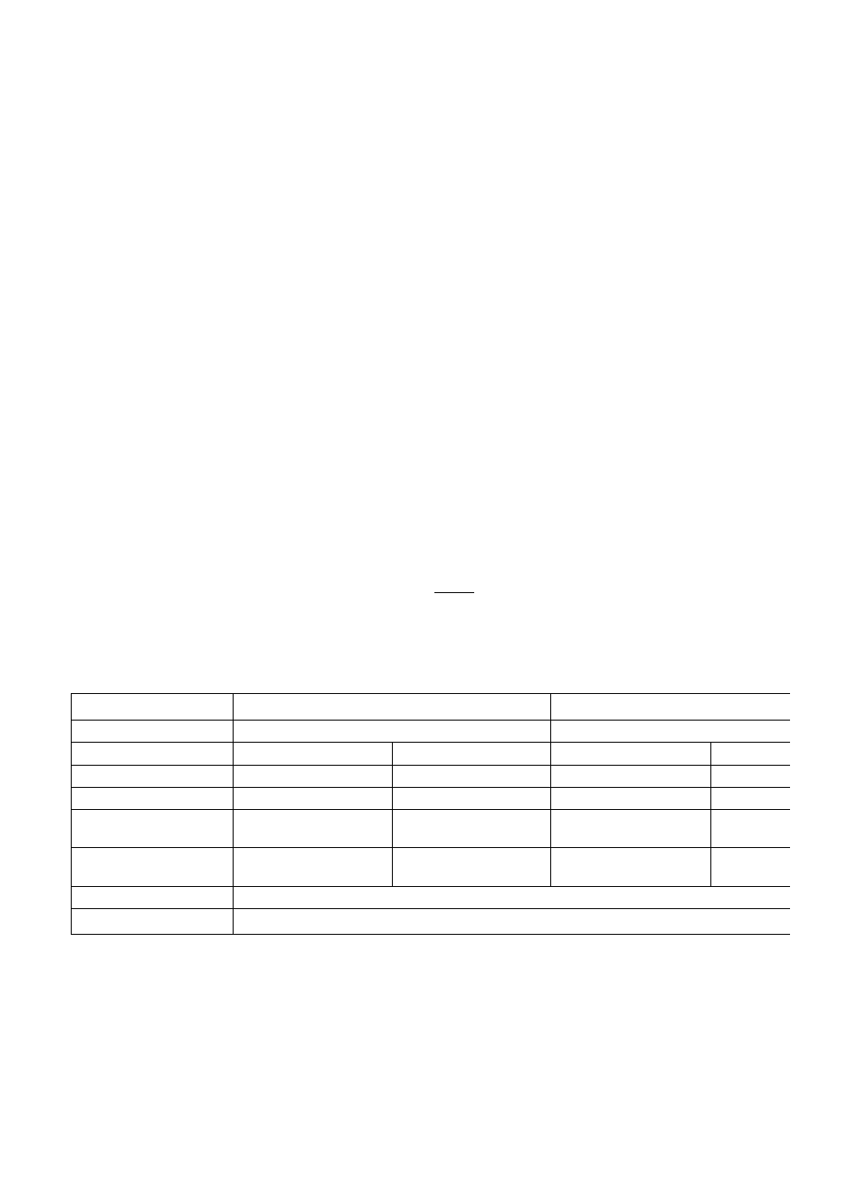
Technical Specification
Models
GC and GE
GC and GE
Gas Type
Natural Gas
LP.G
Range Model
GC
GE
GC
G
Main Burner injector
400
400
180
1i
Pilot Burner Injector
4212
4212
4208
42
Combination Gas Valve
Bypass Screw
1.20 mm
1.20 mm
0.80 mm
0.80
Gas Burner Pressure
4.0
(inch w.g.)
4.0
(inch w.g.)
10.0
(inch w.g.)
1C
(inch
Combination Gas Valve
S.l.T. EUROSIT
Pilot Assembly
JOHNSONS