Adjusting gas input, A. measuring gas flow at meter, Adjusting pressure regulator – Bryant Outdoor Heating Unit 379A User Manual
Page 6
Attention! The text in this document has been recognized automatically. To view the original document, you can use the "Original mode".
Adjusting Gas Input
The gas input must be checked and adjusted, if
necessary, to agree with that shown on the unit rating
plate (150,000 Btuh). The burners are equipped with
fixed orifices. The burners on natural gas units use
No. 41 drill size orifices while the burners on the
propane units are equipped with No. 54 drill size
orifices.
The natural gas unit is equipped with an A639 gas
valve and a combination regulator/shutoff valve. The
propane gas unit uses an A639 gas valve but is not
equipped with a regulator. The regulator for propane
units is located at the supply tank.
CAUTION: The unit may be run for short periods
with the panels removed. Prolonged operation with
the panels removed should not be attempted.
One of the two following methods may be used to ad
just the gas input on a natural gas unit.
A. Measuring Gas Flow at Meter
All other gas appliances must be turned off when
measuring the gas flow at meter to adjust the gas in
put. Proceed as follows when using this method.
1. Determine the number of seconds required for the
gas meter test dial to complete one revolution.
2. Divide 3600 by the number of seconds in Step 1.
3. Multiply the result in Step 2 by the number of cubic
feet of gas flow per hour.
4. Multiply the result of Step 3 by the Btu heating
value of the gas (consult local utility for value). This
is the total measured Btu/hr input.
Compare this value with the one shown on the rating
plate.
Example: Suppose the size of the test dial is 2 cubic
feet; it takes 50 seconds for the dial to complete one
revolution; heating value of the gas is 1050 Btu per
cubic foot. Proceed as follows:
(a) 50 seconds to complete one revolution.
(b) 3600 divided by 50 equals 72.
(c) 72x2 = 144 cubic feet per hour of gas flow.
(d) 144x1050 = 151,200 Btuh input.
Only minor changes should have to be made at the
pressure regulator to bring it within the rated input of
the unit.
B. Using Water Manometer
When using a water manometer to measure the gas
manifold pressure, proceed as follows to adjust the
gas input.
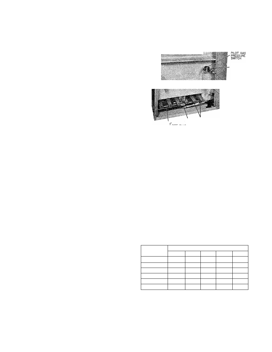
1. Turn off gas to unit.
2. Remove the 1/8-inch pipe plug on the furnace
manifold and connect manometer here. See Figure 6.
3. Turn on gas to unit. With the burners fired, adjust
the pressure regulator to obtain the correct manifold
pressure as shown in Table IV. Check with local gas
utility for Btu value and specific gravity of gas in the
area.
39379D36
PILOT
GAS COCK
COMBINATION
REGULATOR-
SHUTOFF
VALVE
' GAS VALVE
PILOT BURNERS
A72154
Figure 6—Front View of Partially Disassembled
48W-379A
4. Remove manometer from manifold and replace the
1/8-inch pipe plug removed in Step 2 above.
Example: Heating value of gas is 1050 Btu and
specific gravity of gas is 0.63.
(a) From Table IV, the manifold pressure required
for 150,000 Btuh input is 2.8 inches water column.
(b) Set manifold pressure to 2.8 inches w.c. by ad
justing gas pressure regulator adjusting screw.
If required manifold pressure exceeds 3.3 inches w.c.
or is less than 2.7 inches w.c., the burner orifices
should be sized according to unit requirements. Con
sult your Bryant Distributor.
CAUTION: Do not redrill orificesunder any cir
cumstances.
TABLE IV — MANIFOLD PRESSURES
(Inches w.c.)
BTU
Specific Gravity
Value
0.59
0.61
0.63
0.65
0.67
900
3.6
3.7
3.8
3.9
950
3.2
3.3
3.4
3.5
3.6
1000
2.9
3.0
3.1
3.2
3.3
1025
2.8
2.9
3.0
3.1
3.2
1050
2.6
2.7
2.8
2.9
3.0
1100
2.4
2.5
2.6
2.7
2.8
Adjusting Pressure Regulator
If measured and rated input are not approximately
the same, the gas pressure regulator may be adjusted
as follows:
To increase input. Remove regulator sealing cap
and turn gas pressure regulator adjusting screw
clockwise.
To decrease input. Remove regulator sealing cap
6
—