V. coil connections, Vi. electrical connections – Bryant Outdoor Heating Unit 379A User Manual
Page 4
Attention! The text in this document has been recognized automatically. To view the original document, you can use the "Original mode".
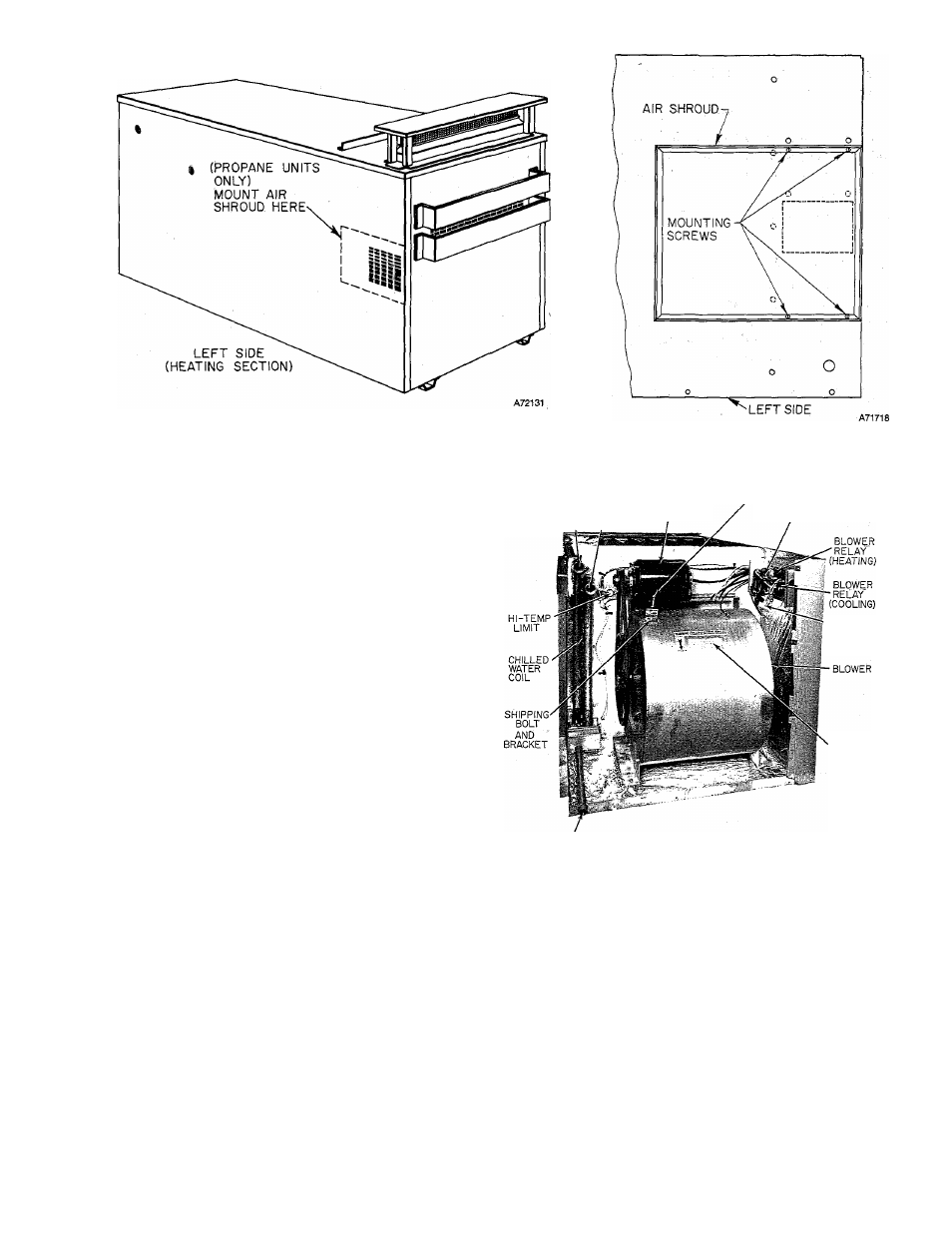
Figure 4—Mounting Air Shroud on Propane Unit
An air shroud is also shipped with propane units only.
Install these items as follows:
1. Remove the cover from the vent opening on the
unit.
2. Remove the top plate from the vent cap assembly
(held by 4 sheet metal screws).
3. Use the screws supplied with the assembly to fasten
the base section of the vent cap assembly to the top
cover of the unit (the unit top is predrilled to receive
the screws).
4. Reattach top plate removed in step 2.
5. Remove the 3 self-tapping screws located ap
proximately 7 inches behind the vent cap. Use these
screws to attach the sheet metal angle to the unit top
cover at this location.
6. Use the screws enclosed in the air shroud package
to mount the air shroud as shown in Figure 4
(propane units only).
V. COIL CONNECTIONS
Figure 5 is a rear view photo of a partially disassem
bled Model 48W-379A unit.
The coil location and chilled water connections for
both the 48W- and 60W-379A are the same for both
units. These two models differ only in the size of the
factory installed chilled water coil.
Two 2-3/8-inch diameter holes are provided in the
right rear corner panel for the chilled water piping en
trance to the unit.
NOTE: Two packaged vinyl grommets are shipped
loose in the blower compartment. Insert one grommet
in each of the 2-3/8-inch corner panel holes.
Route the chilled water piping through the two grom
mets and connect to the two 1-inch F.P.T. connectors
on the coil header. Refer to Figure 5 for chilled water
inlet and outlet connections.
CHILLED WATER
CONNECTIONS
1 /
IN OUT
BELT TENSION
ADJUSTING SCREW ■
BLOWER MOTOR
TRANSFORMER
POWER
CONNECTIONS
TAG
OILING
LABEL
CONDENSATE
DRAIN CONNECTION
Figure 5—Rear View of Partially
Disassembled 48W -379A
Refer to the chiller installation instructions for per
tinent information concerning type and size of piping,,
length of pipe permissible, type of freeze protection,
and chilled water additive required.
VI. ELECTRICAL CONNECTIONS
CAUTION: Before proceeding with the electrical con
nections, check the power supply to be sure that the
voltage, frequency, and phase correspond to that
specified on the unit rating plate.
All electrical connections are to be made in ac
cordance with the National Electrical Code and the
39379D36
-4-