Save these instructions, Switch fig – Black & Decker 4010 User Manual
Page 3
Attention! The text in this document has been recognized automatically. To view the original document, you can use the "Original mode".
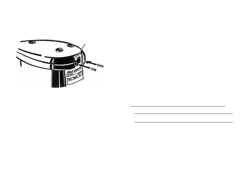
To operate unit, press right side of rocker switch. A white mark should appear to indicate
switch is in the
“on”
position. To stop unit, press left side of rocker switch. The white mark
should no longer be visible.
SWITCH
FIG. ?
HOLE PUNCH OPERATION (FIG, 8)
1. Remove the metal guide and the hole-puncher from the paper holder.
2. Place the paper^ grain upwards on the holder so that the paper is in contact with the
stop.
3. Place the metal guide above the paper so that it is correctly positioned in relation to the
holder.
4. With the aid of the holepuncher, make holes by pressing firmly through the guide and
the paper.
5. Take out the paper, checking that all the holes are clean and match the sender per
fectly.
6. If the holepuncher, after a considerable period of use, produces poor holes, then it is
essential to sharpen or replace it.
SPECIAL SAFETY INSTRUCTIONS FOR SANDERS
Always wear eye protection and a respirator when sanding.
DOUBLE INSULATION
Your Sander is DOUBLE-INSULATED to give you added safety. This means that it is con
structed throughout with TWO separate “layers” of electrical insulation or one DOUBLE
thickness of insulation between you and the tool’s electrical system.
Tools built with this insulation system are not intended to be grounded. As a result, your
Drill is equipped with a two-prong plug which permits you to use extension cords without
concern for maintaining a ground connection.
NOTE DOUBLE-INSULATION does not take the place of normal safety precautions when
operating this tool. The insulation system is for added protection against injury resulting
from a possible electrical insulation failure within the tool.
CAUTION: When servicing Double insulated Tools. USE ONLY IDENTICAL RE
PLACEMENT PARTS. Repair or replace damaged cords.
EXTENSION CORDS
Double insulated tools have 2 wire cords, and can be used with 2 wire or 3 wire extension
cords. Only round jacketed extension cords should be used, and we recommend that they
be listed by Underwriters Laboratories (U.L) (C.S.A. in Canada). If the extension will be
used outside, the cord must be suitable for outdoor use. Any cord marked as outdoor can
also be used for indoor work.
An extension cord must have adequate wire size (AWG or American Wire Gauge) for
safety, and to prevent loss of power and overheating. The smaller the gauge number of
the wire, the greater the capacity of the cable, that is 16 gauge has more capacity than 18
gauge. When using more than one extension to make up the total length, be sure each in
dividual extension contains at least the minimum wire size.
To determine the minimum wire size required, refer to the chart below.
............ CHART FOR MINIMUM WIRE SIZE
CORPS ^
NAME PLATE
TOTAL EXTENSION CORD LENGTH - FEET
RATING - AMPS 25
50
75
100
125
150
175
200
0-10.0
18
18
16
16
1 4
1 4
12
12
10.1-13.0
16
16
14
1 4
14
12
12
1 2
13.1-15.0
14
14
12
12
12
12
12
_
Before using an extension cord, inspect it for loose or exposed wires, damaged insulation,
and defective fittings. Make any needed repairs or replace the cord if necessary. Black &
Decker has extension cords available that are U.L (C.S.A in Canada) listed for outdoor
use,
MOTOR
Your Black & Decker tool is powered by a B & D built motor. Be sure your power supply
agrees with the nameplate marking.
Volts 50/60 Hz or “AC only” means your tool must be operated only with alternating cur
rent and never with direct current. Volts DC-60Hz or AC/DC means your tool may be op
erated with either alternating or direct current.
Voltage decrease of more than 10% will cause loss of power and overheating. All B&D
tools are factory tested. If this tool does not operate, check the power supply.
SAVE THESE INSTRUCTIONS