Save these instructions, Chain brake operation, Bar & chain installation – Black & Decker 3803-10 User Manual
Page 7
Attention! The text in this document has been recognized automatically. To view the original document, you can use the "Original mode".
CHAIN BRAKE OPERATION
The brake is actuated if pressure is applied against the lever when, as in the event of
“kickback,” the operator’s hand strikes the lever. When the brake is actuated, chain
movement stops abruptly and the power supply to the motor is cut off.
CAUTION: Purpose of the CHAIN BRAKE is to reduce the possibility of injury due to
“kickback” but it cannot provide the measure of protection intended if the saw is
operated carelessly.
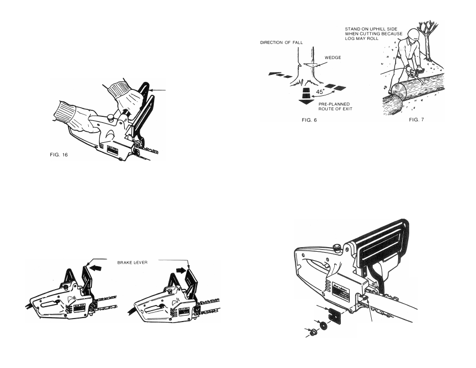
CAUTION; Hand placement is important. ALWAYS grip front handle directly behind the
handguard/chain brake lever (See FIG. 16).
FRONT HANDLE
The CHAIN BRAKE is disengaged (the chain can move) when the brake lever is pulled
back and locked. (FIG. 17). This is the normal running position. The CHAIN BRAKE is
engaged (chain is stopped) when the brake lever is in the forward position. (FIG. 18)
Before cutting with your saw, test the CHAIN BRAKE as follows:
1. Place the saw on a firm flat surface.
2. Follow the correct procedures to operate the saw.
3. Grasp the rear handle firmly with the right hand.
4. With the left hand, hold the front handle (not the CHAIN BRAKE lever) firmly. (FIG.
16)
5. Squeeze the trigger so that the chain begins to move, then activate (push forward) the
CHAIN BRAKE lever (FIG. 18).
CAUTION: Activate the CHAIN BRAKE SLOWLY and DELIBERATELY. Be careful to
keep the chain from touching any surface: don't let saw tip forward.
6. The chain should stop abruptly.
NOTE: If the chain doesn't stop, shut off the motor. Take the saw to your B & D dealer for
repair or replacement of the CHAIN BRAKE.
HANDGUARD.
chain
-
fig
. 17
FIG. 18
10
SAVE THESE INSTRUCTIONS
BAR & CHAIN INSTALLATION
All Models.
REMOVE LOOSE PARTS from the plastic bag. The combination wrench is the only tool
you need,
STUDY THE ILLUSTRATIONS to become familiar with the parts and their positions
(FIG 8).
BE CERTAIN SAW IS UNPLUGGED from power supply.
SUPPORT SAW on its side with sprocket facing up.
CHECK THAT THE ADJUSTER SCREW ASSEMBLY IS IN ITS SLOT, Ensure that the
adjuster nut is positioned as far to the rear as possible with the lug pointing outwards
ready to engage in the hole in the guide bar. (FIG, 9) Wearing gloves, mount the chain on
the guide bar with the cutters facing forward on the top of the bar (FIG. 11)
FIG.8
PLATE-BAR
WASHER-FLAT
NUT-BAR
GUIDE BAR
MOUNTING BOLT