Black & Decker WM2000 User Manual
Page 7
Attention! The text in this document has been recognized automatically. To view the original document, you can use the "Original mode".
' : • • .' >; - ■ *1».
■S'r .■■vi--
■&■’-; ■ ■ •■ --■
Fig. 8
The swivel jaw can be locked in six
different 45° positions 3 front facing and 3
rear facing.
Follow the procedure shown in 90°
clamping fig. 6 ensuring that the metal
pins of the cam locks are released into the
holes provided for 45° angles. (E) fig. 1.
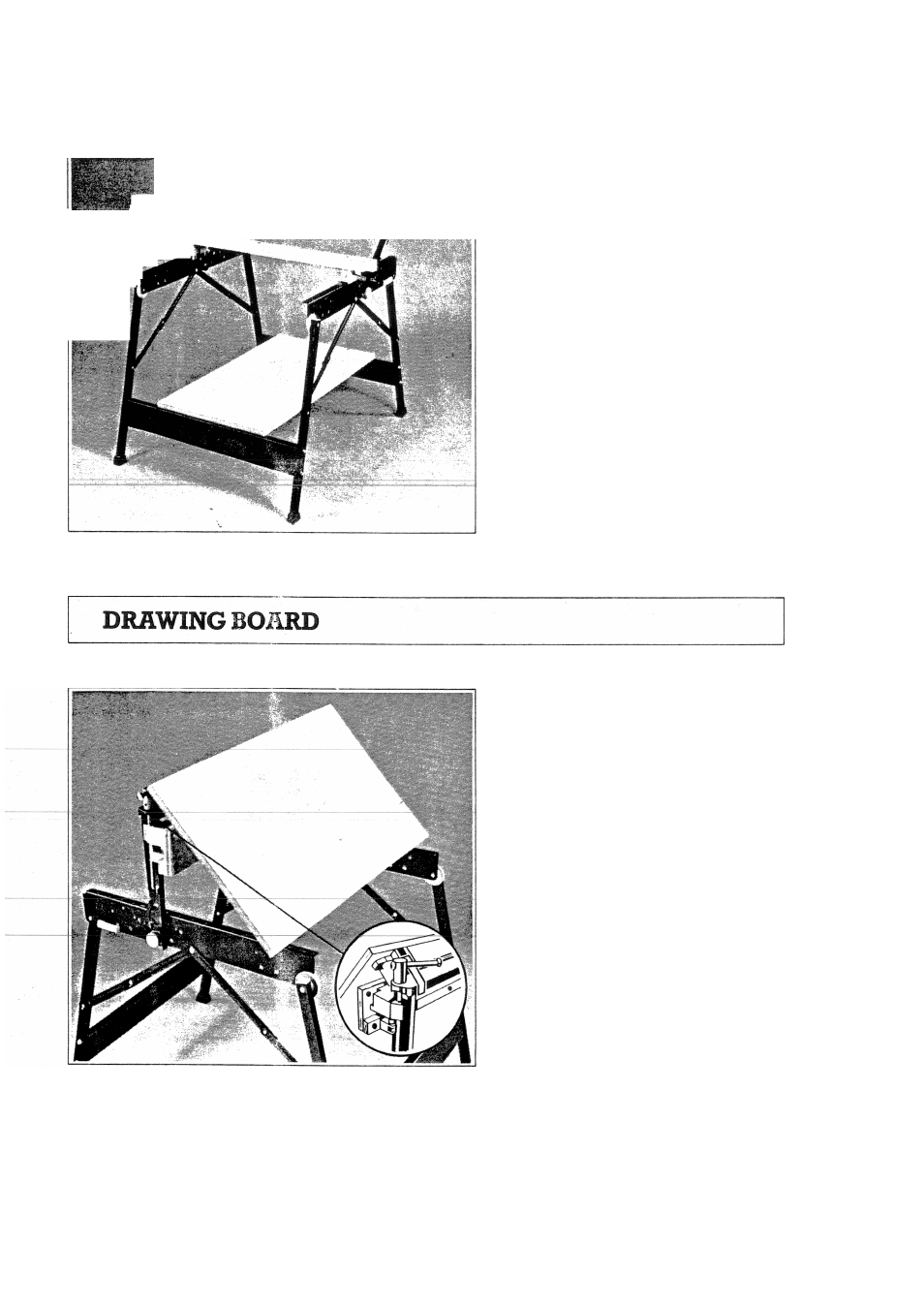
The WM2000 can be converted into a
drawing board with the aid of the two
metal brackets provided. Follow the set
up procedure in fig. 6.90° vice adjustment.
Set the swivelling vice jaw as shown in fig.
9.
The removable vice jaw should be
either removed as shown in fig. 9. or
positioned at the front end of the parallel
rails.
Lock the metal brackets into the plastic
base supports (rectangtdar supports) of
the centre board and clip over the front
top cross member. As shown, fig. 9.
Fig. 9