Assembly instructions, Standard equipment – Black & Decker WM2000 User Manual
Page 4
Attention! The text in this document has been recognized automatically. To view the original document, you can use the "Original mode".
ASSEMBLY INSTRUCTIONS
I vviiji me legs iii the
7cr:icm pcGiticr; lock
ihe meia.1 strats as sho'v/n
Remove the WM2000 from packaging
ensuring that the centreboard is clamped
securely between the vice jaws.
Place the WM2000 on floor as shown in
fig. 2 and release the two retaining
catches and open the first pair of legs,
with the legs in vertical position lock &e
metal struts as shown.
Release the remaining set of legs and
foUow above procedure.
Note: Before placing the WM2000 in the
upright position ensuring all four metal
struts are locked securely.
Fig. 2
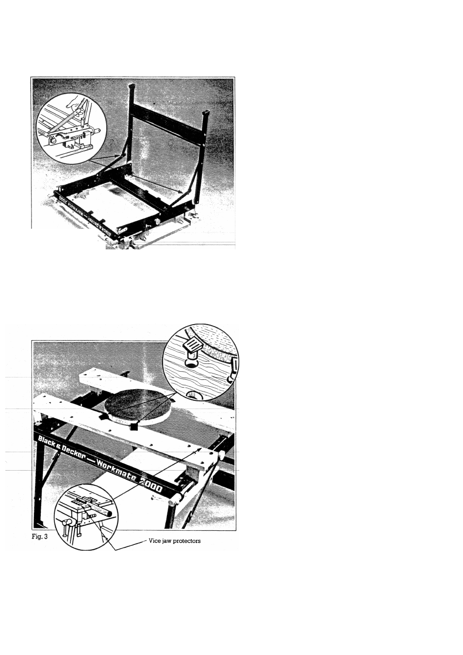
STANDARD EQUIPMENT
Each WM2000 is supplied with:
(A)
Four vice pegs - ideal for clamping
irregular shaped work pieces safely fig. 3.
(B)
Two jaw protectors - ideal for
gripping
pipes
etc,
securely
either
vertically or horizontally.
(C)
Two metal drawing board brackets
as shown in fig. 9.