Nvc series b-vent – Vermont Casting NVC36 User Manual
Page 8
8
NVC Series B-Vent
20000194
The fireplace, when installed, must be
electrically connected and grounded in
accordance with local codes or, in the
absence of local codes, with the current
CSA C22.1 Canadian Electrical Code
For USA installations follow the local
codes and the national electrical code
ANSI/NFPA No. 70.
It is strongly suggested that the wiring of
the EB-1 Electrical Junction Box be
carried out by a licensed electrician.
Ensure that the power to the supply line
has been disconnected before commenc-
ing this procedure.
The EB-1 Electrical junction box has been supplied
standard on the DVRT 36/39/43 models to allow for the
easy installation of an optional fan kits.
To connect the EB-1 box to the house electrical supply
follow the steps below.
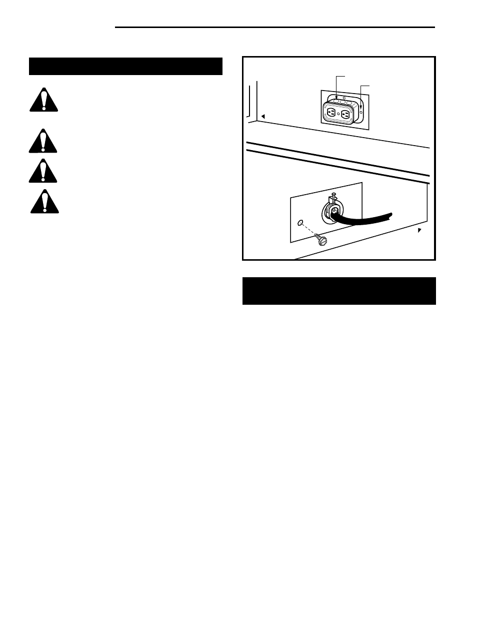
1. Unscrew the retaining screw from the EB-1 base
plate (Fig. 8) and remove the EB-1 assembly from
the fireplace.
2. Remove the front cover of the EB-1 box.
3 Remove the plug socket assembly from the EB-1 box.
4. Feed the supply line in from the outside through the
cable clamp. (Fig. 8)
5. Connect black wire of the power supply line to the
brass screw (polarized) of the socket assembly.
6. Connect the white wire of the power line to the
chrome screw of the socket assembly.
7. Connect the ground wire of the supply line to the
green screw of the socket assembly.
8. Refit the socket assembly back into the electrical
box and replace the cover plate. Secure the cable
with the clamp on the outside of the unit to prevent
strain on the connections.
9. The EB-1 electrical junction box is now ready to
supply power to the FK12 or FK24 fan kits if fitted.
EB-1 Electrical Box
Outside
Electrical Box
Front of Unit
Inside
Front of Unit
Retaining Screw
FP580
Fig. 8 EB-1 receptacle.
Install the Venting System,
Flashing and Termination
Refer to venting installation instructions provided by the
B-Vent manufacturer.
Refer to Figure 1, Page 3 to locate chimney center line
dimension from a combustible back wall.
• Minimum vertical chimney height — 12 feet
(3.65m).
• Maximum vertical height — 40 feet (12m).
• Minimum height with two elbows — 12 feet
(3.65m)
• Elbow requirements allow a maximum of two
90 degree elbows or four 45 degree elbows
per installation. (Two 45 degree elbows =
One 90 degree elbow.) See venting chart for
proper elbow offset runs.
For firestop positioning, refer to Figure 9. Only one (1)
firestop required per frame. NOTE: A firestop is not
required at the roof.