Drilling in masonry, Drill accessories, Maximum recommended capacities – Black & Decker 5065 User Manual
Page 3: Carbon removing brushes, 3" wire cup brush, Hammer/drill selector, Chuck key holder, Chuck, Holder
Attention! The text in this document has been recognized automatically. To view the original document, you can use the "Original mode".
Drilling in Masonry
Refer to the same list of instructions
under ‘DRILLING’', but use percussion
Masonry drill bits only. Drill in masonry
only. Keep even force on the drill but not
so much that you crack the brittle
materials. A smooth, even flow of dust
indicates the proper drilling rate.
Drill Accessories
The accessories listed in this manua,
are available at extra cost from your local
dealer or Black & Decker Service Center.
A complete listing o1 service centers is
included on tne owner’s registration card
packed witri your tool.
If you need assistance in locating
any accessory, please coniac:: Black &
Decker, (U.S.' me.. User Services
Department, 626 Hanover Pike, P.O. Box
618, Hampstead, MD 21074-0618.
Every Black S Decker loo' is oi the
highest quality. !i you wish to contact us
regarding this product, please call toll free
between 8:00 a.m. and 5:00 p.m. EST
Monday through Friday. 1 -800-762-6672
Recommended accessories io" you:
Drill are shown in this manual (CAUTION:
The use of any other accessory might be
hazardous.) For safety in use, the
following accessories should be useo onlv
in si.zes UD to the maximums snowri in
table below.
Maximum
Recommended
Capacities
DRILL CAPACITY
R.P.M.
0-900/0-2200
BITS, METAL DRILLING
1/2"
WOOD, FLAT BORING
1"
BITS, MASONRY DRILLING 3/4"
HOLE SAWS
1-1/8"
WIRE WHEEL BRUSHES-
WIRE CUP BRUSHES —
BUFFING WHEELS
— 4" Dia. Max.
3" Dia. Max.
— 3" Dia. Max.
RUBBER BACKING-
PADS
■ 4-5/8" Dia. Max.
ACCESSORY MUST BE RATED FOR
USE AT SPEED EQUAL TO OR
HIGHER THAN N.AMEPLATE R.P.M.
OF TOOL WITH WHICH IT IS BEING
USED.
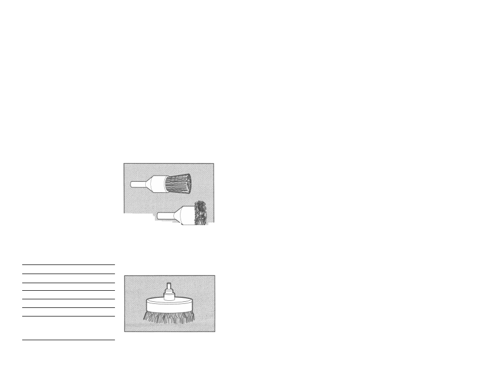
Carbon Removing
Brushes
Made of tempered-steel wire; used
with drills to remove rust and scale from
metals. Leaves a burnished surface.
A. Heavy-duty solid wire-filled brush.
B. Side-flare brusii for close corner
work
C. Hollow-core flare-bottoiTi brush.
Small cleaning brush. (No: shown.'
3" Wire Cup Brush
Use in cleaning and removing rust,
scaie, old pain.. (Straight chuck snank,.
Maximum safe RPM—5,000.
mil
Your Hammer Drill is equipped with
dual range speed control for greater
versatility. To change from one range to
the other, turn the too! off and then rotate
the range control dial. shov\/n in Figure 3,
to the desired position. Turn Hie dial so
that the symbol 1 is toward the chuck for
low speed (0-90C RPM). If you want high
speed (0-2200 RPM) lurn the dial so thal
the symbol li is toward the chuck
NO"!"E; It may sometimes be necessary
to manually turn the spindle slightly
when shitting from one ranae to anot'nei.
DO NOT SHIFT WHEN THE TOOL IS
RUNNING OR COASTING.
The tool mus- be fully engaged into
range I or range II. Make sure that the
selector is noi somewhere between the
two; damage to the unit may result.
IHilil
i toward the chuck. For hammering, align
\ the hammer symbol with the chuck, as
stiown in the figure.
NOTE: The selector must be in either
drill or hammer mode at all times. There
are no operable positions between the
two.
Hammer/Drill Selector
To switch the tool from the drilling mode j
to the hammering moae io- vice-versa) ;
rotate the dial, snown m Figure 4, so that |
tne desirec position is accomolisheo. For |
straigh: driliing. align the drÜ! bit symbol
Ciici lii ief
UNPLUG DRILL. Open chuck jaws
and inserì shank of bi; aboui inio
chuck. Tighten chuck collar by hand.
Place chuck key in each of the three
•loles,
and iigkaen ir clockwise direction.
It’s important to tighten chuck with all
three holes to prevent slippage of drill bit
in chuck. To release bit, turn chuck key
coLinierciocKwise in
jusi one hoie, ther
loosen chuck by hand.
Chuck
Key
Holder
1. Push double-hole end of holder
through slot in other end of Holder.
(Figure 5).
2. Slip loop over electric plug and draw
loop tight around cord (Figure 6).
3. Push ends of Chuck Key Handle
through two holes in end of Holder
(Figure 7).