Flue connection and infilling thermostat – Charnwood SLX20 User Manual
Page 10
Replace the back fireplate, the side fireplates, the front
firebar and the throat plate.
Connect the boiler to the heating system ensuring that the
flow pipe rises from the boiler. Fill the system with water
and check for leaks.
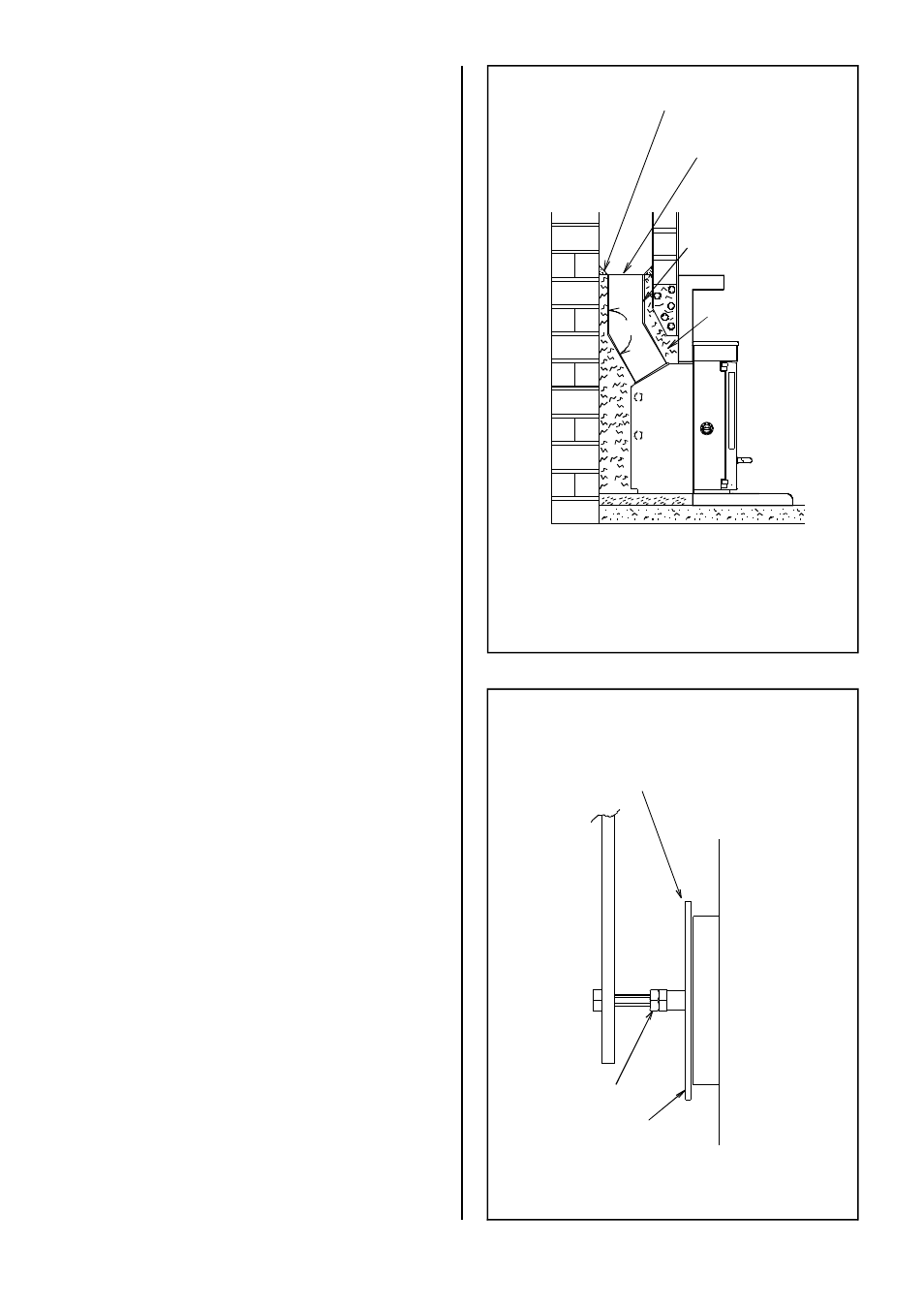
Make the flue connection with the special 150° elbow, Part
No. 010/AV12. Please note that this item is ordered
separately from the appliance. The legs of the elbow may be
cut on site to suit the chimney. Also note that the legs of the
elbow are different lengths to enable some situations to be
catered for by turning the elbow around.
The end of the flue pipe must line up with the centre-line of
the chimney, and must also extend to the point where the
chimney narrows to its final size. Any large voids must be
filled and flaunched to the flue pipe to ensure that all soot
deposits can be cleared when the appliance is swept, and to
prevent problems with the operation of the appliance.
Ensure that the flue pipe is not obstructed or restricted in
any way and that all joints are well sealed.
Before infilling cover the front of the appliance to protect it.
Ensure that the flue pipe is central and then fill the space
between the body of the appliance and the structural
brickwork with vermiculite (e.g. Micafil or similar) concrete.
Ensure that there are no air pockets. The recommended
mix is six volumes of vermiculite to one volume of portland
cement throughly mixed together. Enough water should be
added so that no more than one or two drops of water are
released when a handful ofmixture is squeezed.
After filling with vermiculite flaunch the top of the flue
connector pipe to the chimney with lime mortar. Ensure
that the flue pipe is well sealed to the chimney.
Make good hole(s) in the chimney breast making sure that it
is completely airtight. A typical installation is shown in fig. 5.
In most installations it will be possible to sweep the chimney
through the appliance. If this is not possible then some
alternative means (such as a soot door) must be provided.
The free inset method of installation may be used instead of
infilling. Details are available on request.
Before lighting the fire check the cold setting distance of the
thermostat.
With the control knob at the minimum setting the flap
should be just closed as shown in Fig. 6. To adjust the
distance slacken the locking nut and adjust as necessary.
When set correctly re-tighten the locking nut. Ensure that
the flap opens and closes freely as the knob is turned.
FLUE CONNECTION
AND INFILLING
THERMOSTAT
Vermiculite
Infill
Flaunching
Take Flue Pipe
Up To Narrowest
Part Of Chimney.
150° Elbow
Part No. 010/AV12
Fig. 5. Typical Installation
150°
Page 10
SLX20 9.03
Thermostat Flap
Locking Nut
Flap Just Closed With
Knob Set To Minimum
Fig. 6. Thermostat Setting