Assembly instructions – MTD 110-111-300 User Manual
Page 4
Attention! The text in this document has been recognized automatically. To view the original document, you can use the "Original mode".
ASSEMBLY INSTRUCTIONS
1
1
B
B
K
V
E
FIGURE 1.
FIGURE 2.
Lower
Handle (H)
NOTE
This unit is shipped WITHOUT GAS
OLINE or OIL. After assembly, see
operating section of this manual for
proper fuel and engine oil recom
mendations.
Your new mower is shipped preassembled with
the exception of the handle.
Contents of Hardware Pack: (See Figure 1.)
-A (5) Hex Bolts 1/4-20
X
1.50" Long
B (6) Hex Lock Nuts V4-20 Thread
C (1) Hex Bolt 1/4-20 X 1.75" Long
D (2) Cable Ties
E (2) Hairpin Cotters
F (2) Hand Grips (not shown)
Tools Required for Assembly:
(1) Adjustable Wrench
(1) 7/16" Open End or Box Wrench
(1) 3/4" Open End or Box Wrench
Loose Parts in Carton: (See Figure 2.)
-H (1) Lower Handle
(2) Upper Handles
I
1
.
2
.
Remove lawn mower and all parts from the
carton. Make certain that all loose parts and
literature have been removed before the car
ton is discarded.
Extend throttle control assembly which is at
tached to engine at the rear of the mower and
place on floor.
3.
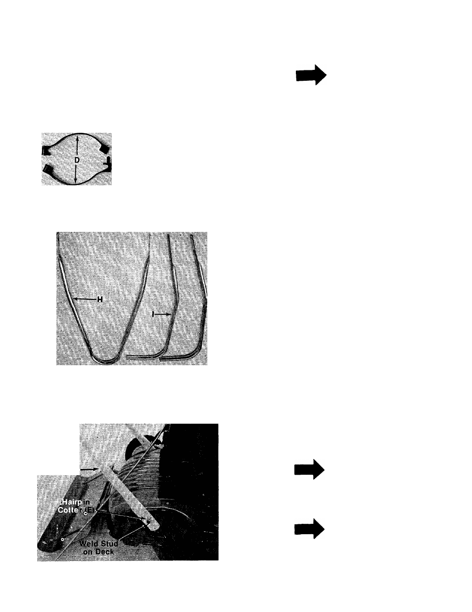
FIGURE 3.
^CAUTION
Do not bend or kink control wires.
Place TOP SLOTTED hole in lower handle (H)
■over studs located in front of each rear wheel.
Secure with hairpin cotter (E) provided in hard
ware pack. See figure 3.
NOTE
It may be necessary to bend the
ends of the lower handle inward
slightly to assure a snug fit against
the deck mounting area.
NOTE
Figure 3 was photographed with the
rear wheel removed for clarity. It is
not necessary to removt* wheel for
handle assembly.