Note, Contents of hardware pack, Assembly instructions – MTD 310-181-000 User Manual
Page 4
Attention! The text in this document has been recognized automatically. To view the original document, you can use the "Original mode".
Hooked in
Middle
Adjustment
Hole
FIGURE 2
Upper
Chute
B
Hand Knob.
ASSEMBLY
INSTRUCTIONS
NOTE
This unit is shipped WITHOUT GAS
OLINE or OIL. See operation section
of this manual for proper fuel and engine
oil recommendations.
Contents of Hardware Pack:
(2) Ignition Keys (One may be on snow thrower)
1. Remove the snow thrower and loose parts from
carton. Make certain all parts and literature have
been removed from the carton before carton is
discarded.
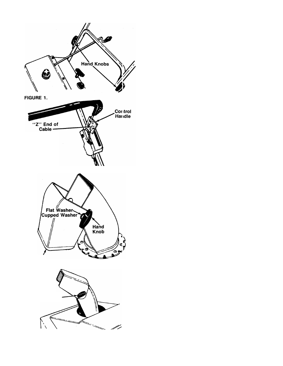
2. Loosen the hand knob on each side of the handle.
Pull handle up into operating position. See Figure
1. Retighten the hand knob.
3. Connect the control cable to the control handle by
hooking the “Z” end of the control cable into the
-------middle hole in control handle. See figure 2.
NOTE
The three holes in the control handle
provide adjustment for the belt ten
sion. Refer to adjustment section of
this
manual
when
adjustment
is
needed.
4. The snow thrower has been shipped with the up
per chute pivoted all the way down. Assemble as
follows.
a. Remove the hand knob, cupped washer, flat
washer and carriage bolt from the upper chute.
--------- See figure 3A.
b. Pivot the upper chute up so there is no gap be
tween the upper and lower chute. See figure
3B. Secure with hardware just removed.
5. Make certain
all
nuts and bolts are tightened
securely.
FIGURE 3.