Safe operation practices (continued), Blade brakeiclutch maintenance, Note – MTD 114-074-000 User Manual
Page 4: Lower handle, Assembly, Contents of hardware pack: (see figure 1)
Attention! The text in this document has been recognized automatically. To view the original document, you can use the "Original mode".
SAFE OPERATION PRACTICES (Continued)
BLADE BRAKEICLUTCH MAINTENANCE
NOTE: Any required repair work on the biade
brake/clutch should be performed by an author- 3.
ized service dealer. If you cannot locate an author
ized service dealer, contact the manufact jrer as
set forth on your copy of the Owner’s Registration
Card.
1. The blade brake/clutch hand control is a safe
ty device. Never attempt to bypass its opera
tion. Doing so makes the safety device in
operative and may result in personal injury
through contact with the rotating blade. This 4.
hand control must operate freely in both direc
tions.
2. Striking a solid object can cause daniage to
the blade brake/clutch or to the engine crank
shaft. Extensive vibration of the mowei during
operation is an indication of damage and the
unit
should
be
promptly
inspected
and
repaired.
A leak in the lower engine crankshaft oil seal
could expose the blade brake/clutch friction
pads to excess oil resulting in blade or brake
slippage, which could increase the stopping
time of the blade. Oil collection on the floor
beneath the mower during storage may be an
indication of an oil seal leak. The unit should
be checked by an authorized service dealer.
Periodically inspect the inner control cable in
the area where it attaches to the hand control.
If the cable becomes frayed, it could cause
the blade brake/clutch to operate improperly.
Also, be careful to avoid pinching the blade
brake/clutch control cable when storing the
handle.
NOTE
This unit is'shipped WITHOUT GAS
OLINE or OIL. After assembly, see
separate engine manual for proper
fuel and engine oil recommenda
tions.
ww
-B
,_F
FIGURE 1.
Lower Handle-
4
у
Hairpin i
Cotter (A)
in Inner
Hole
Handle
Bracket
ASSEMBLY
Contents of hardware pack: (See figure 1)
A (2) Hairpin Cotters
В (2) Curved Carriage Bolts 1.38" Long
C (2) Lock Washers 5/16" I.D.
D (2) Hex Nuts 5/16-18 Thread
E (2) Cable Ties
F (4) Shoulder Bolts*
— G (4) Belleville Washers 3/8" I.D. x 7/8" O.D.*
H (4) Belleville Washers 3/8" I.D. x 1-1/8" O.D.*
I (4) Hex Nuts 3/8-16 Thread*
*Units with wheeis not assembied.
1. Remove the iawn mower, ioose parts, hard
ware pack and iiterature from the carton.
Make certain all parts and literature have been
removed before the carton is discarded.
2. Extend the throttle control cable (attached to
the upper handle) and the blade brake/clutch
cable (attached to the blade brake/clutch
beneath the deck) and place on the floor. Be
careful not to bend or kink control cables.
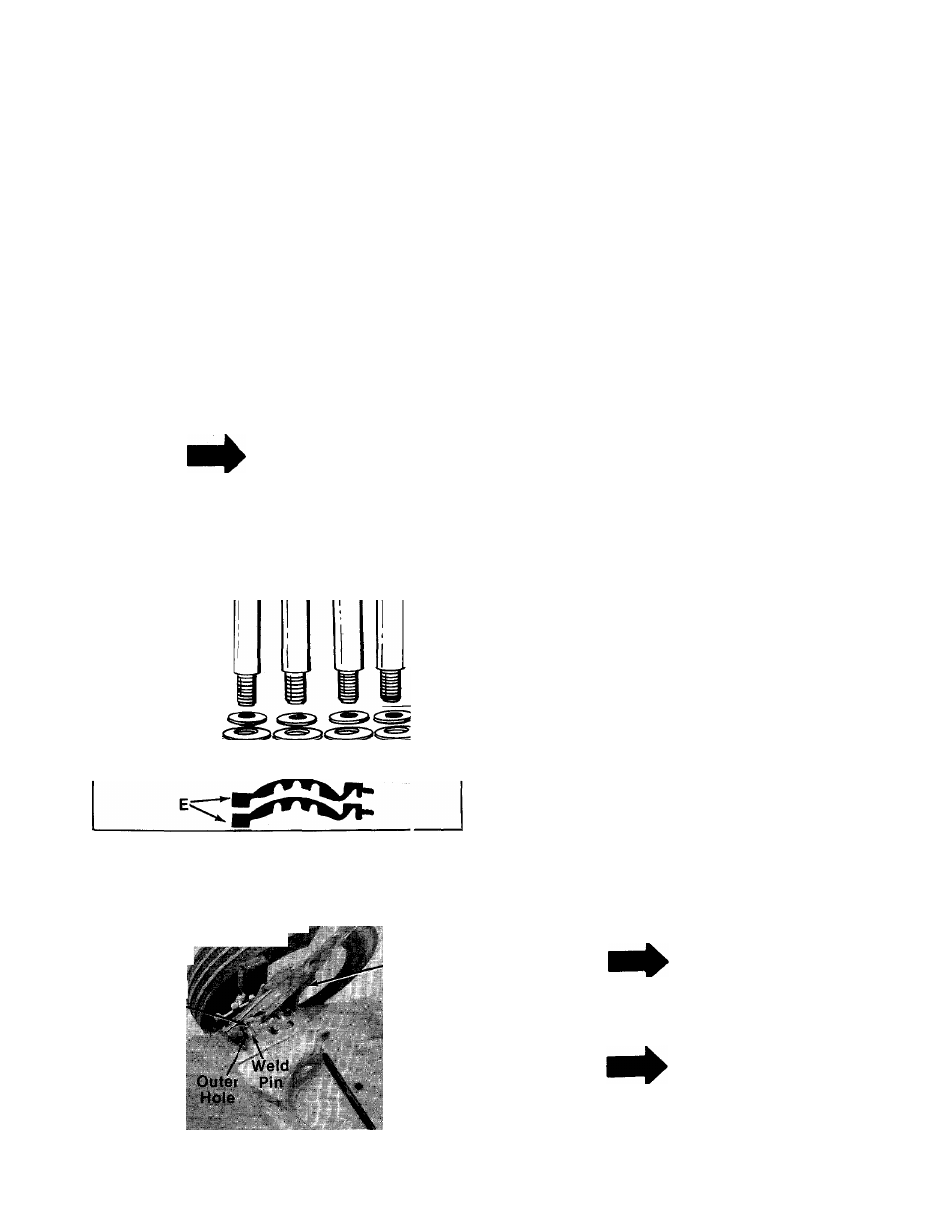
3. Place lower handle in position over weld pins
in handle mount brackets on deck. Make cer
tain the instruction label on the lower handle
can be read from the operating position.
Secure by placing two hairpin cotters (A) in in-
------ ner hole on weld pins. See figure 2.
FIGURE 2.
NOTE
It may be "necessary to bend the
ends of the lower handle outward
slightly to obtain a snug fit against
the bracket.
NOTE
There are two (2) holes in the handle
mount brackets. Place hairpin cot
ter in the inner hole for operation.
The outer hole is for storage.