Securing the cables (hardware d), Attaching the starter rope (hardware c), Attaching the rear wheels (hardware f) – MTD 112-518R000 User Manual
Page 6
Attention! The text in this document has been recognized automatically. To view the original document, you can use the "Original mode".
Truss
MacP ine
Sen iw
FIGURE 4.
3. Place the control box on the upper handle just
below the end of the control handle as shown in
— figure 4. Secure with hardware removed in step
one by placing hex lock nut into the indent on the
inside of the control box. Screw the truss machine
screw into the hex lock nut.
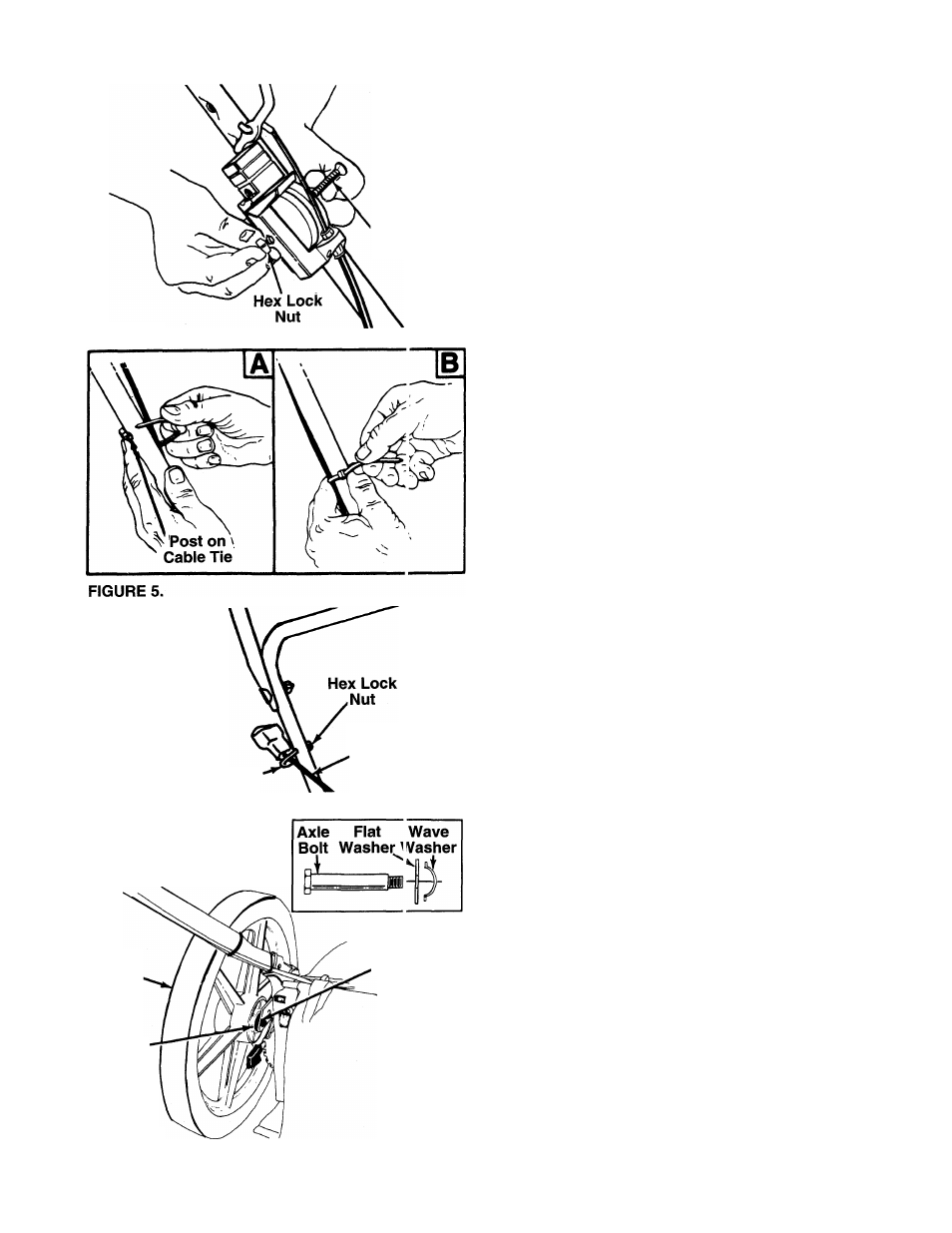
SECURING THE CABLES (Hardware D)
Secure all cables to the left side of the handle as fol
lows.
WARNING: When attaching the control
cables, the cables must be routed to
avoid contact with all sharp edges and
hot surfaces to prevent damage to the
cables, which will render the controls
inoperative.
Insert posts on cable ties into holes provided on
the lower handle. The holes may be either on the
— inside or outside of the handles. See figure 5A.
2. Secure the cables with the cable ties. See figure
5B. Trim excess ends of cable ties.
A
1
,
Rope Guide
Starter
Rope
FIGURE 6.
Rear
Wheel
Cupped
Washer
FIGURE 7.
Rear He ile
In Five it
Bar
ATTACHING THE STARTER ROPE (Hardware C)
1. The starter rope is inside the top of the engine.
Additional rope may be wound around the starter
handle. If so, unwind the rope from the handle.
2.
With the spark plug wire disconnected and
grounded, depress the blade control handle and
pull the rope out of the engine.
-3. Place the rope guide around the starter rope, so
the rope guide is positioned as shown (bends
downward slightly). Insert the rope guide through
the right side of the lower handle, and secure with
hex lock nut. See figure 6.
ATTACHING THE REAR WHEELS (Hardware F)
-Assemble the rear wheels as follows. See figure 7.
1. Move the wheel height adjusters so the deck is in
the lowest cutting position.
2. Lift the rear of the unit up and block securely.
3. Place one large flat washer on axle bolt, then the
wave washer (cupped side against the flat wash
er as shown in figure 7, inset).
4.
Insert axle bolt through one rear wheel. Place
cupped washer on axle bolt (crowned side of
washer goes against the wheel).
5.
Thread axle bolt into rear hole of pivot bar.
Tighten securely.
6. Assemble other rear wheel in the same manner.