Assembly instructions – MTD 241-670A User Manual
Page 4
Attention! The text in this document has been recognized automatically. To view the original document, you can use the "Original mode".
ASSEMBLY
INSTRUCTIONS
CONTENTS OF HARDWARE PACK
(A)
4
Hex Bolts 1/4-20x 1.25" Long
(B)
13
Hex Cent. Lock Nuts 1/4-20 Thread
(Model 241-670A Only)
16
Hex Cent. Lock Nuts 1/4-20 Thread
(Model 241-680A Only)
(C)
2
Flat Washers .285" I.D. x .62 O.D. x .059
(D)
4
Flat Washers .285" I.D. x 1.25" O.D. x .060
(E)
3
Hex Bolts 1/4-20
X
.50" Long
(F)
3
Flat Washers .28" I.D. x .75" O.D. x .063
(G)
4
Flat Washers .344" I.D. x .88" O.D. x .063
(H)
4
Thumb Nuts 5/16-18 Thread
(1)
1
Deflector
(J)
2
Hex Bolts 1/4-20
X
1.50" Long*
(K)
2
Cable Ties*
(U
1
Ferrule*
(M)
1
Control Lever*
(N)
1
Flat Washer .510" I.D. x .75" O.D.*
(0)
1
Spacer*
*Self-Propelled Model 241-680A Only
1.
Place the upper handle in position. Fasten with
four (4) hex bolts (A) and hex center lock nuts
(B) provided.
2.
Place the air duct liner (studded end first) into
the elbow of air duct. See figure 1.
\
■
B
/
FIGURE 1
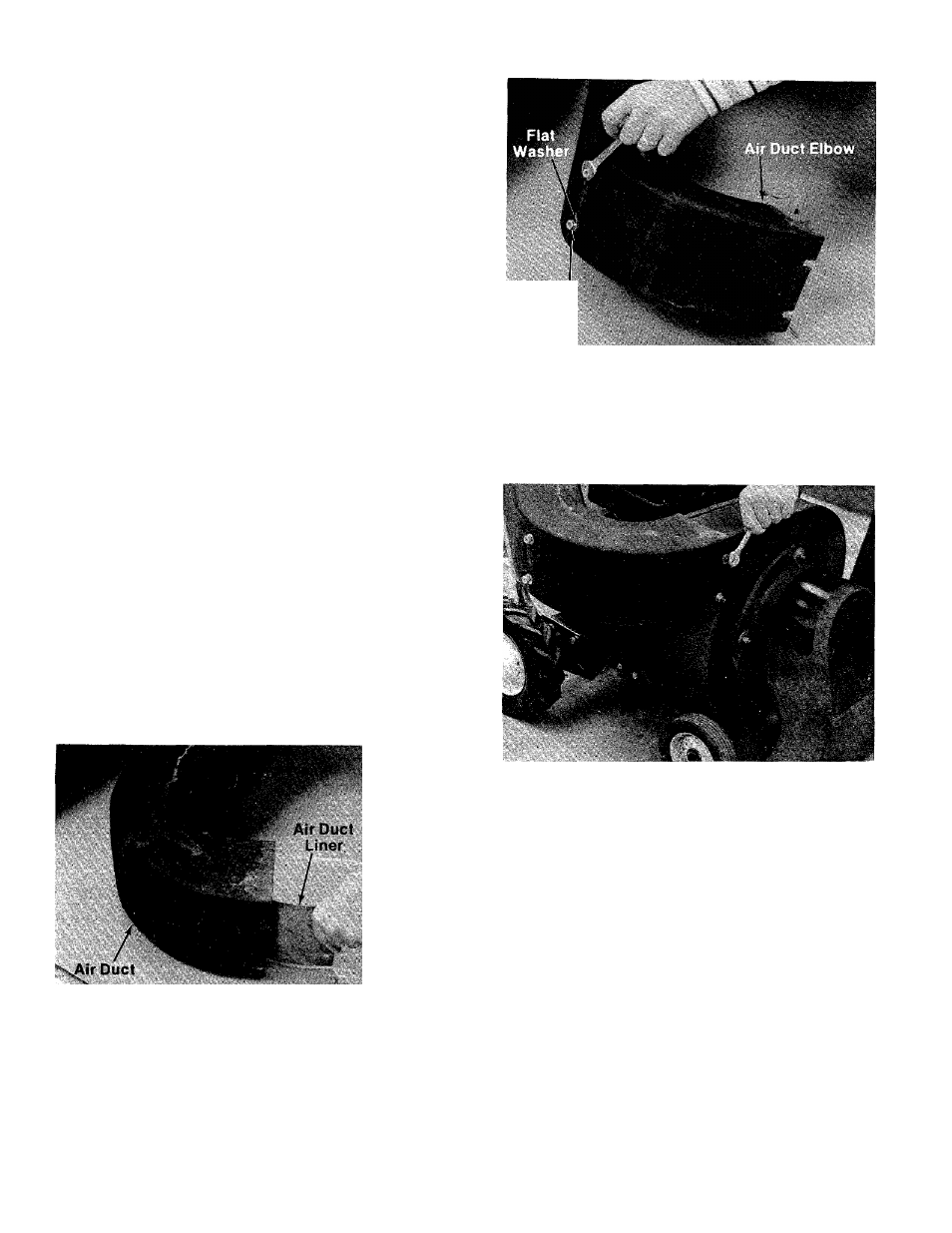
3.
Insert studs of air duct liner through holes in
air duct. Thread on two (2) flat washers (C) and
hex nuts (B) several turns—DO NOT TIGHTEN.
See figure 2.
Hex Nut
FIGURE 2
4.
Place the air duct in position on the blower
housing. Fasten with four (4) flat washers (D)
and hex nuts (B). See figure 3.
FIGURE 3
5.
Tighten the two hex nuts on the air duct liner
studs at the air duct elbow.
6.
Slide the vacuum bag over the back of the upper
handle and snap the four flaps to hold the bag.
7.
Fasten the deflector (I) on the top of the air duct
with three hex bolts (E), flat washers (F) and hex
nuts (B). Refer to illustration on page 6.
8. Slide the bag over the air duct.
9.
Fasten the nozzle to the front of the vacuum
with four flat washers (G) and thumb nuts (H)
provided.
Use the following steps on the self propelled unit only
(Model 241-680A).
10. Fasten the throttle control to the right hand sidf
of the upper handle with one hex bolt (J) and
hex center lock nut (B) provided.