Assembly instructions – MTD 110-530 User Manual
Page 4
Attention! The text in this document has been recognized automatically. To view the original document, you can use the "Original mode".
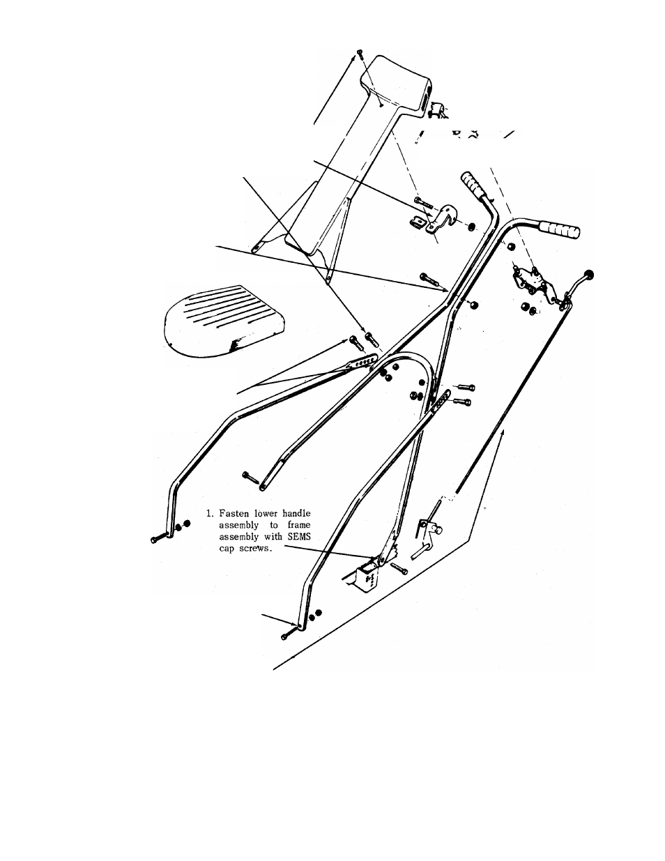
ASSEMBLY INSTRUCTIONS
8. Fasten control panel to upper handle with cap screws and
locknuts at lower holes and truss head screw through upper
hole. Tighten all nuts and bolts.
5. Assemble speed nut to clamp bracket. Assembly clamp,
bracket to upper handles with long yellow bolt and nut as
shown.
2. Assemble upper handle parts with cap
screws and locknuts as shown —^
BLADE SPINDLE COVER
7. Assemble throttle control to
handle panel with two sheet
metal screws.
j
6. Assemble lockout bracket
assembly to upper handle.
/
A
/ Tighten nuts
securely.
4. Assemble upper handles and lower handle
supports to lower handle assembly with
cap screws and locknuts. Position sup
ports for most convenient height.
Use lower holes only.
3.
Attach lower handle supports to frame assembly
with cap screws, lockwashers and hex nuts
9. Blade Engagement Assembly-
a. Remove Blade Spindle Cover by removing three screws.
b. Move brake lever to rear position so belt is slack.
c. Insert ferrule into blade bracket assembly from the left.
d. Screw rod into ferrule.
e. Assemble control handle to control rod as shown.
f. Adjust control rod. A slight pressure should be needed to operate lockout lever.
Too much pressure can break lever assembly or control rods. Readjust control
rods if pressure is too great.
g. Replace Blade Spindle Cover.
FORM N0.770 1847D