Assembly instructions – MTD 110-530A User Manual
Page 4
Attention! The text in this document has been recognized automatically. To view the original document, you can use the "Original mode".
ASSEMBLY INSTRUCTIONS
NOTE: Follow instructions in numerical order.
7. Assemble lockout bracket
as shown.
8
. Fasten lockout lever to
lockout bracket assembly
with hex screw, lock
washer and hex nut.
1. Assemble throttle
control to handle
panel.
11. Slip hand grips on
the upper end of
each handle. They
will slip on more
easily if you first
s o a k
t h e m i n
warm
soapy
wa
ter.
b.
c.
d.
e.
f.
g-
9. Blade Engagement Assembly,
a. Remove blade spindle cover by
removing three screws.
Move brake lever to rear posi
tion so belt is slack.
Insert ferrule into blade bracket
assembly from the left.
Screw rod into ferrule.
Assemble control handle to
control rod as shown.
Adjust
control
rod.
A
slight
pressure should be needed to
operate
lockout
lever.
Too
much pressure can break lever
assembly or control rod. Read
just control rod if pressure is
too great.
Replace blade spindle cover.
3.
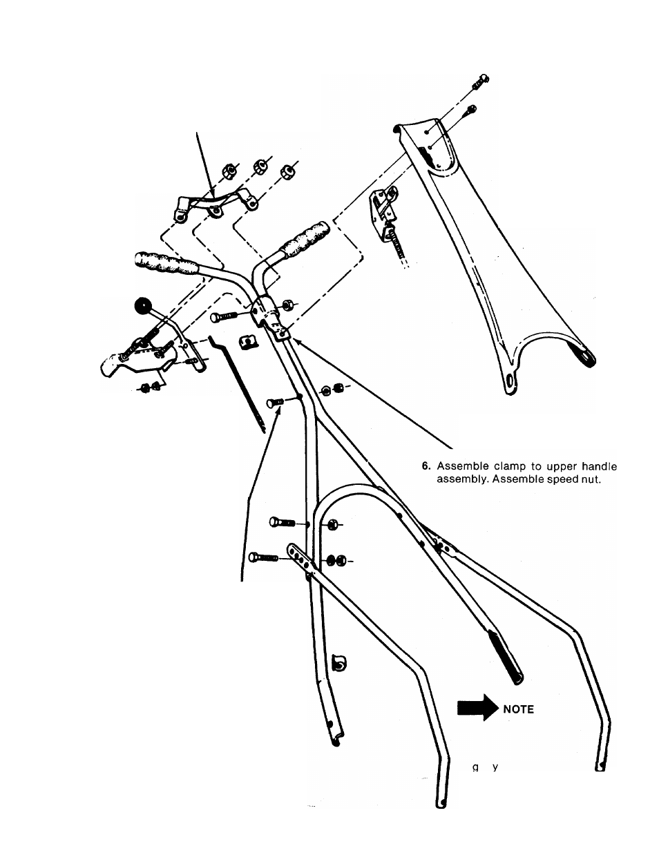
Assemble two upper handles. Use this bolt
only.
5. Position upper handle assembly on lower han
dle.
Adjust
handle
supports
as
desired.
Fasten upper handle assembly and handle
supports to lower handle.
2.
Assemble lower handle to mower. Secure
throttle control wire to lower handle with
cable tie. Cut off end of tie.
4. Assemble two handle supports to mower.
12. Check ALL nuts and bolts for correct
tightness.
10. Assemble handle
panel to handle.
It may be necessary to
bend the ends of the
lower
handle
inward
slightly
to
assure
a
snug
fit
against
the
deck mounting area.