Tramsmis¥l£>f4 rbtjiüvâup? i'^klement, To adjust steering wheel alignment, Front wheel e-in/camber – Poulan 169482 User Manual
Page 23: Remove wheel for repairs, See fig. 27), To start engine with a weat eahery (see fig. 28, Nc 2i, Tramsmis¥l£>f4 rbtjiüvâup? i, Lement, Wheel
Attention! The text in this document has been recognized automatically. To view the original document, you can use the "Original mode".
H ‘‘.NSAILE IIOTIOr ' «TOOL LE¥ER
NEUTRAL ADJUSTME
Fig. 26)
The motion control lever has been preset at the factory and
adjustment should not be necessary.
Loosen adjustment bolt in front of the right rear wheel,
and lightly tighten.
Start engine and move motion control lever until tractor
does not move forward or backward.
Hold motion control lever in that position and turn
engine off.
While holding motion control lever in place, loosen the
adjustment bolt.
Move motion control lever to the neutral (N) (lock gate)
position.
Tighten adjustment bolt securely.
NOTE: If additional clearance is needed to get to adjust
ment bolt, move mower deck height to the lowest position.
After above adjustment is made, if the tractor still creeps
forward or backward while motion control lever is in neutral
position, follow these steps;
•
Loosen the adjustment bolt.
•
Move the motion control lever 1/4 to 1/2 inch in the
direction it is trying to creep.
•
Tighten adjustment bolt securely.
•
Start engine and test.
•
If tractor still crtpps rtpr
if
yc^ttpr
unhl --dtLfied.
MOTION i'ONTRuL
LE/FR — A
NEÜÎRAL
LOCK GATE
ADJUSTMENT
BO
l
T
nc 2i
TRAMSMiS¥l£>f4 RbTjIüVÂUP? I'^
k
LEMENT
LfijUid /
j
U
i
(
I
m
:
c
r
gu
> n x
al
v
ivic*
n
rf-pir {tiTif-fii,'i ~h< ul t ' f.bX * ifit t ieir H llaiion -I'i'i
brfurt opi ratitiu the ti ut T
m
‘f UhC L t RANSMI. -
SlOh’
in
the Upnaiun o-iction o ihis ma.iuai.
TO
ADJUST
STEERING WHEEL ALIGNMENT
If steering wheel crossbars are not horizontal (left to right)
when wheels are positioned straight forward, remove steer
ing wheel and reassemble per instructions in the Assembly
section of this manual.
FRONT
WHEEL
E-IN/CAMBER
The front wheel toe-in and camber are not adjustable on
your tractor. If damage has occurred to affect the front
wheel toe-in or camber, contact your nearest authorized
service center/department.
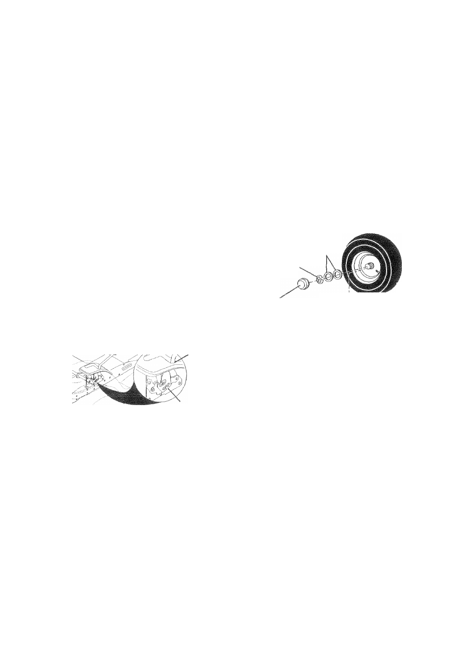
REMOVE WHEEL FOR REPAIRS
(See Fig. 27)
Block up axle securely.
Remove axle cover, retaining ring and washers to allow
wheel removal (rear Vi/heel contains a square key - Do
not lose).
Repair tire and reassemble.
On rear wheels only; align grooves in rear wheel hub
and axle. Insert square key.
Replace washers and snap retaining lim securely in
axle groove.
Replace axle cover.
NOTE: To seal tire punctures and prevent flat tires due to
slow leaks, tire sealant may be purchased from your local
parts dealer. Tire sealant also prevents tire dry rot and
corrosion.
WASHERS
RETAINING
RING-
AXLE COVER
TO
SQUARE KEY
(REAR WHEEL ONLY)
FIG.
27
TO START ENGINE WITH A WEAT EAHERY
(See Fig. 28
A
CAUTION; Lead-acid batteries gener
ate explosive gases. Keep sparks, flame
and smoking materials away from bat
teries. Always wear eye protection
when around batteries.
23
If your battery is too weak to start the enqine, it should be
recharged. (See “BATTERY" in the CUSTOMER RESPON
SIBILITIES section of this manual).
If “jumper cables" are used for emergency starting, follow
this procedure;
IMPORTANT: YOUR TRACTOR IS EQUIPPED WITH A 12
VOLT NEGATIVE GROUNDED SYSTEM. THE OTHER
VEHICLE MUST ALSO BE A 12 VOLT NEGATIVE
GROUNDED SYSTEM. DO NOT USE YOUR TRACTOR
BATTERY TO START OTHER VEHICLES.
TO ATTACH JUMPER CABLES -
•
Connect each end of the RED cable to the POSITIVE
(+) terminal of each battery, taking care not to short
against chassis.
•
Connect one end of the BLACK cable to the NEGA
TIVE (-) terminal of fully charged battery.
•
Connect the other end of the BLACK cable to good
CHASSIS GROUND, away from fuel tank and battery.
TO REMOVE CABLES, REVERSE ORDER -
•
BLACK cable first from chassis and then from the fully
charged battery.
RED
cable last
from
both batteries.