To removb belt guard (see fig. 22), Engine, To adjust carburetor (see fig. 23) – Poulan 163659 User Manual
Page 14: Service and adjustments
Attention! The text in this document has been recognized automatically. To view the original document, you can use the "Original mode".
SERVICE AND ADJUSTMENTS
TO REMOVb BELT GUARD (See Fig. 22)
•
Remove two (2) cap nuts and washers from side of belt
guard.
•
Loosen (do not remove) tine shield nut on underside of
tine shield.
•
Pull belt guard out and away from unit.
•
Replace belt guard by reversing above procedure. Be
sure slot in bottom of belt guard is under head of tine
shield bolt and all nuts are tightened securely.
CAP NUTS
AND WASHERS
BELT
GUARD
TINE
SHIELD
NUT
FIG. 22
ENGINE
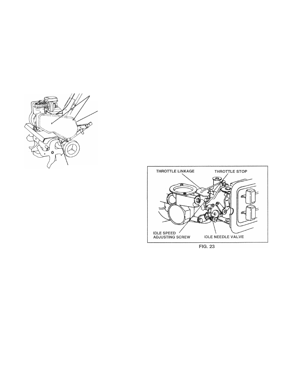
TO ADJUST CARBURETOR (See Fig. 23)
The carburetor has a high speed fixed jet and has been
preset at the factory and adjustment should not be neces
sary. However, minor adjustments may be required to
compensate for differences in fuel, temperature, altitude or
load. If the carburetor does need adjustment, proceed as
follows.
In general, turning the idle needle valve in (clockwise)
decreases the supply of fuel to the engine giving a leaner
fuel/air mixture. Turning the needle valve out (counter
clockwise) increases the supply of fuel to the engine giving
a richer fuel/air mixture.
IMPORTANT:
DAMAGE TO THE NEEDLES AND THE
SEATS IN CARBURETOR MAY RESULT IF SCREWS ARE
TURNED IN TOO TIGHT.
PRELIMINARY SETTING
•
Aircleaner assembly must be assembled to the carbu
retor when making carburetor adjustments.
•
With engine off, turn idle needle valve in (clockwise)
closing it finger tight and then turn valve out (counter
clockwise) 1
-
1/2
turns.
FINAL SETTING
•
Start engine and allow to warm for five minutes. Make
final adjustments with engine running at idle and tine
control lever in “OFF” position.
® With throttle control in “SLOW” position, turn idle needle
valve in (clockwise) until engine begins to die, then turn
out (counterclockwise) until engine runs rough. Turn
valve to a point midway between those two positions.
IDLE HPM ADJUSTMENT
» To adjust idle RPM, rotate throttle linkage counterclock
wise and hold against stop while adjusting idle speed
adjusting screw to obtain 1750 RPM. Release throttle
linkage.
ACCELERATION TEST
• Move throttle control lever from “SLOW” to “FAST”
position. If engine hesitates or dies, turn idle needle
valve out (counterclockwise) 1/8 turn. Repeat test and
continue to adjust, if necessary, until engine acceler
ates smoothly.
High speed stop is factory adjusted. Do not adjust or
damage may result.
IMPORTANT:
NEVER TAMPER WITH THE ENGINE
GOVERNOR. WHICH IS FACTORY SET FOR PROPER
ENGINE SPEED. OVERSPEEDING THE ENGINE ABOVE
THE
FACTORY
HIGH
SPEED
SETTING
CAN
BE
DANGEROUS. IF YOU THINK THE ENGINE-GOVERNED
HIGH
SPEED
NEEDS
ADJUSTING,
CONTACT
YOUR
NEAREST
AUTHORIZED
SERVICE
CENTER/
DEPARTMENT, WHICH HAS THE PROPER EQUIPMENT
AND E X P E R I E N C E T O M A K E A N Y N E C E S S A R Y
ADJUSTMENTS.
16