MTD 314-830A User Manual
Page 3
Attention! The text in this document has been recognized automatically. To view the original document, you can use the "Original mode".
*?>
FIGURE 1.
CONTROLS
Auger Clutch is located on the Left Hand side of the
frame just behind the thrower housing, (Shown in the
disengaged position.) When the handle is up, the aug
er is disengaged. WARNING: Engaging auger clutch
with main clutch already engaged will damage pins
on sprocket hob assembly. Damaged pins cause hard
engagement and clutch malfunction. Do not engage or
disengage
the
auger
clutch
without
first
disengaging
the main clutch. Disengaging the auger clutch allows
you to drive the snow thrower to and from the work
area without the auger turning. (See figure 2.)
FIGURE 2.
Main
Clutch, This clutch shuts off the power to the
wheels and auger. When the handle is up it is in the
disengaged position. Always shot off the main clutch
when
engaging
and
disengaging
the
auger
dutch.
(Shown in the disengaged position.) (See figure 1.)
Grip Clutch. The grip clutch engages and disengages
the drive wheels. To engage the clutch, squeeze the
handle and depress the button to lock it. Squeezing
the handle again will release it. (Shown in the disen
gaged position.) (See figure 3.)
Shift Lever. The shift lever determines the direction
and speed forward of the drive wheels. Always re
lease the grip clutch when shifting gears. (See figure 3.)
Chute Controls. Release the lock and turn the crank
to rotate the chute. Loosen the wing nut to adjust the
deflector. (See figure 3.)
FIGURE 3.
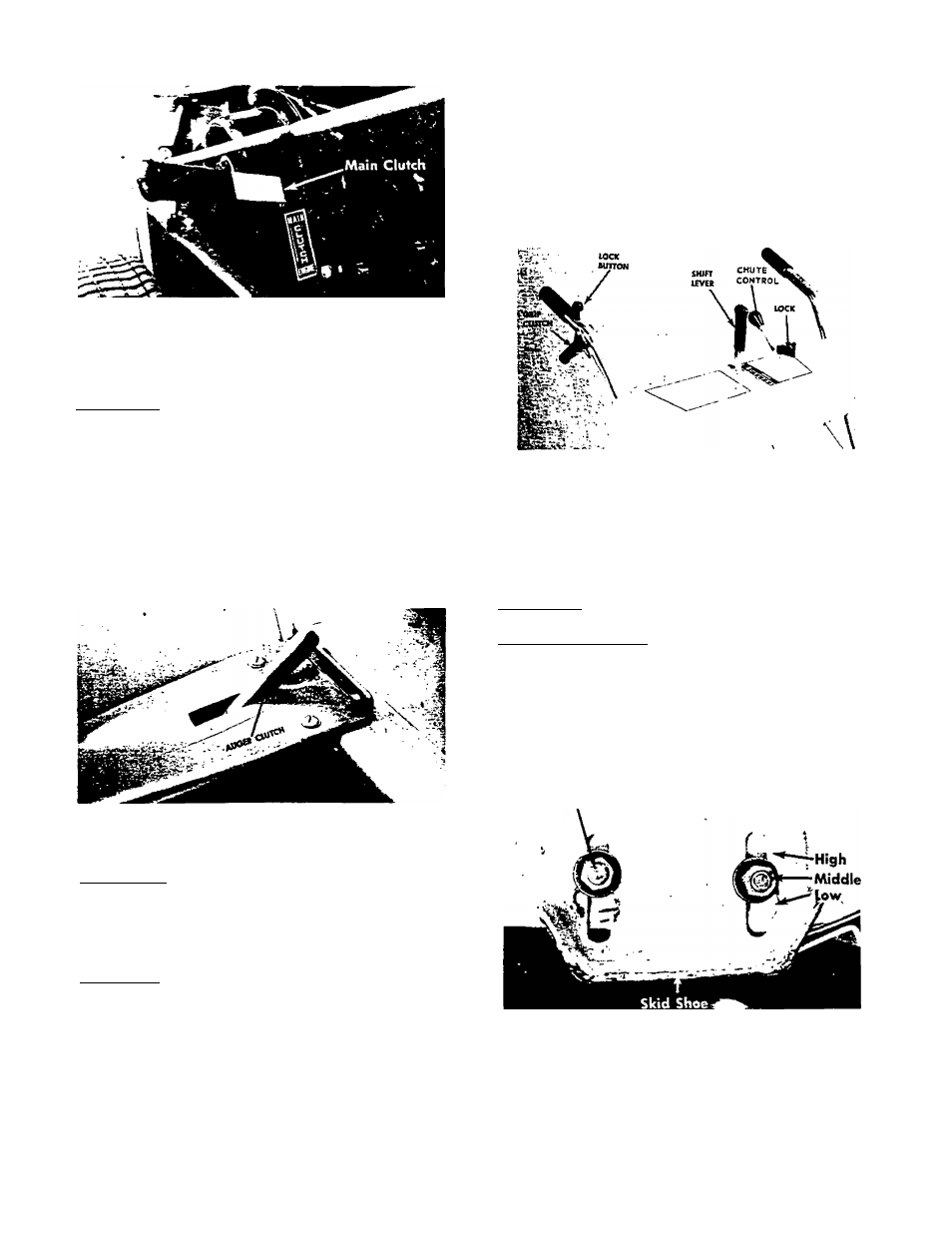
SKID SHOES
The skid shoes on each side of the thrower are adjust
able by loosening the bolts and nuts.
low Position—Close snow removal.
Middle or High Position—Use when road is uneven.
The skid shoes and shave plate should be replaced
when worn.
The skid shoes may be tipped for better operation.
Bolt and Nut
/
FIGURE 4.