D. starter rope, E. oil pump – Poulan 425 User Manual
Page 16
Attention! The text in this document has been recognized automatically. To view the original document, you can use the "Original mode".
D. STARTER ROPE
• Replace a broken starter or a rope that is
badly frayed.
NOTE: A recoil spring lies beneath the pulley and
is under tension. If the recoil spring is dis-
tnrbed, considerable time and effort will be
required to reinstall. For this reason you may
want to let a qualified service dealer handle this
repair. If you try to repair the starter rope and the
recoil spring pops out, take the unit to your dealer.
A
WARNING
Always wear eye protection when servicing the
starter
rope.
The
recoil
spring
beneath
the
pulley is under tension. If the spring pops out,
serious injury can result.
1. Drain the fuel tank.
2. Remove the four screws on the side of the fan
housing. Figure 32 .
3. Separate the fan housing from the unit.
4.
If the starter rope is not broken, release the
spring tension by pulling about 10 inches of
rope from the pulley and catch the rope in the
notch as shown in Hgure 33 .
5.
Turn the pulley counterclockwise until the
spring tension is released.
6. Remove the pulley screw/washer in the center
of the pulley. Figure 34
7. Lift the pulley
carefully
while gently twisting it
counterclocl^se.
Remove
any
remaining
rope.
8. Move away from the fuel tank and melt both
ends of the new rope.
9. Allow each melted end to drip once. Then,
while the rope is still hot, pull each melted end
through a rag to obtain smooth, pointed ends.
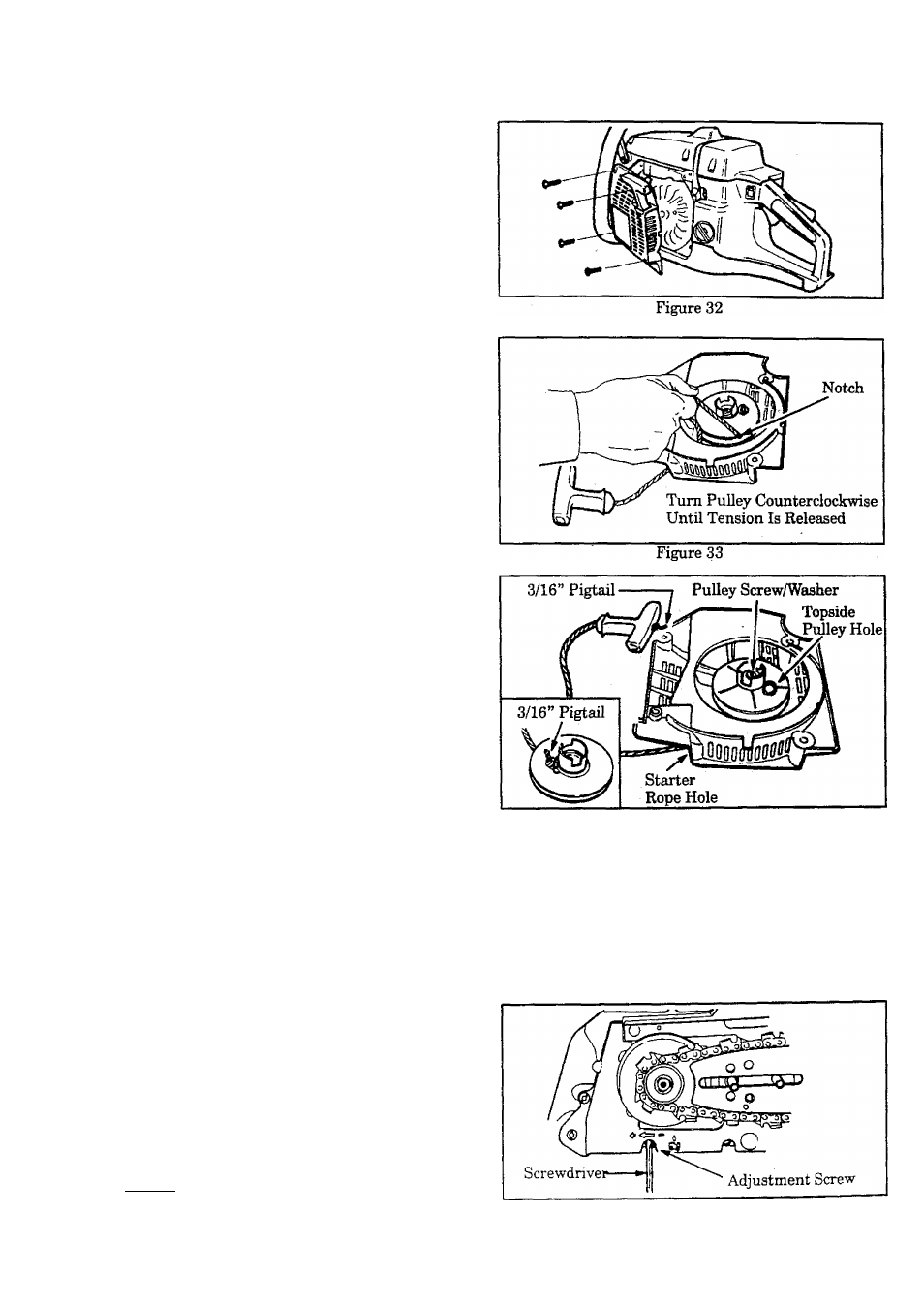
10. Feed the rope through the hole in the handle.
Secure the rope with a knot, leaving about a
3/16” pigtail. Figure 34 .
11. Feed the rope through the round starter rope
hole in the fan housing. Figure 34.
12. Guide the rope inside the pulley, then up
through the pulley hole to the outside. Fig
ure 34 . Secure the rope with a knot, leaving
about a 3/16” pigtail, ^gure 34 (inset).
13. Rewind the rope onto the pulley by turning the
pulley in a counterclockwise direction.
14. Set the pulley into the housing; push it down
and engage the spring.
15. Replace and tighten the pulley screw/washer.
Figure 34
16. Pull out (inside the pulley housing) 10 inches
of rope and catch the rope in the notch in the
pulley. Figure 33.
17. Turn the puHey 2 complete turns clockwise
winding up the spring.
18. Hold the pulley and pull the sterter rope to the
full extent. Let the rope rewind slowly.
19. Reinstall fan housing.
E. OIL PUMP
The oil flow can be varied by turning the adjustment
screw on the crankcase. Figure 35 .
1. Turn the adjustment screw counterclockwise
(to +) to increase the oil supply.
2. Turn the adjustment screw clockwise (to -) to
decrease the oil supply.
NOTE: Never adjust the oil pump when the en
gine is running.
Figure 35
- 1 6