Maintenance (continued) – Troy-Bilt 13096 User Manual
Page 27
Attention! The text in this document has been recognized automatically. To view the original document, you can use the "Original mode".
Maintenance (continued)
• With an assistant, lift fender back and up
off of unit. NOTE: Gear drive units
require gear shift iever to be pul ted in
slightly to clear fender.
Fender Installation
Install fender by reversing removal
sequence. Re-assemble with brake pedal
assembly (I, Fig. 6-12) to outside of brake
arm. Tighten all hardware (C) securely.
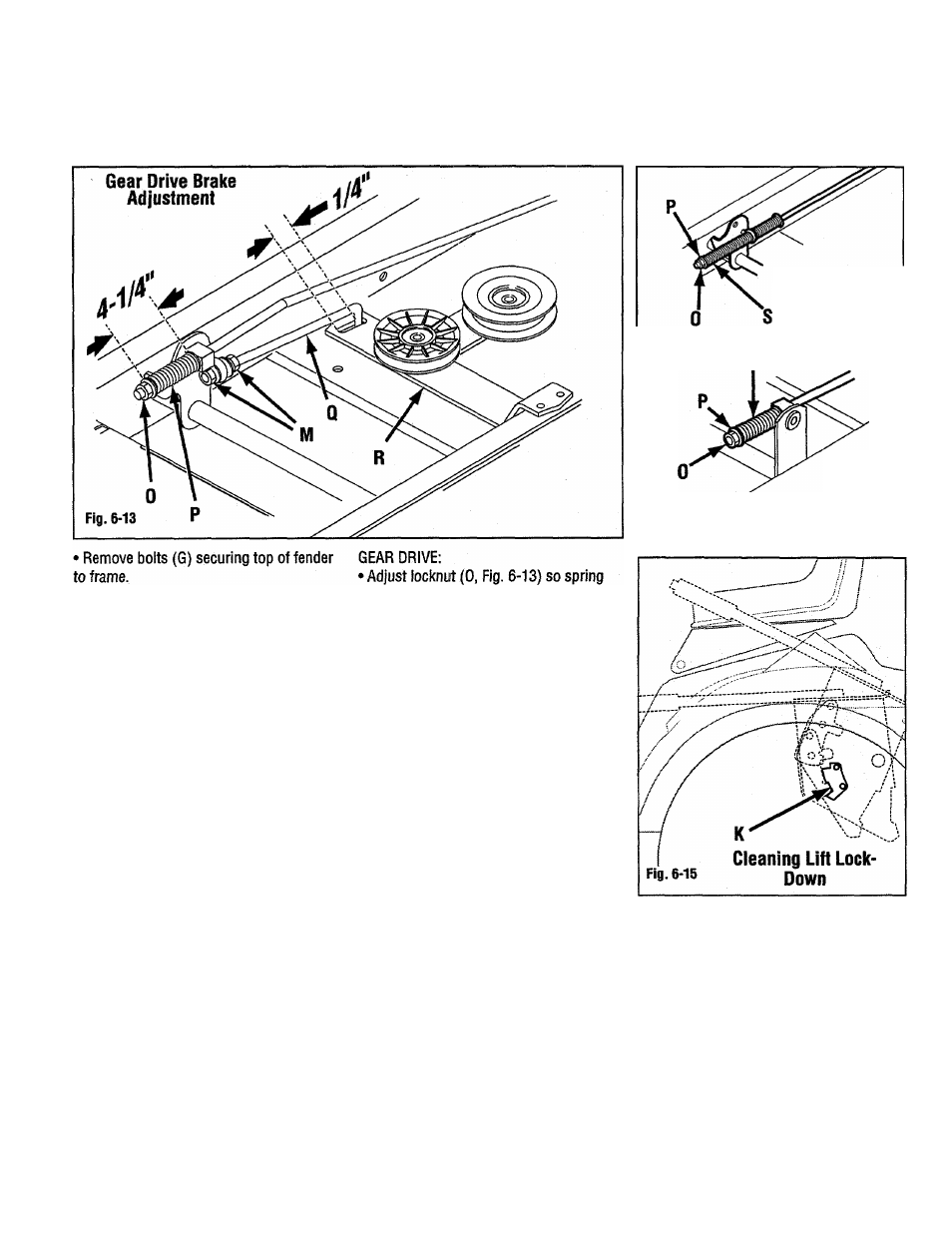
Brake Adjustment
Adjustment is required if brake does not
hold the tractor when parking brake is set.
Adjust brake in disengaged position.
(P) measures 4-1/4” long.
• Adjust locknuts (M) so a gap of 1/4”
exists between clutch rod (Q) and front of
slot in idler bracket (R).
HYDROSTATIC DRIVE:
• Adjust locknut (0. Fig. 6-14) so a gap of
1/16” exists between washer (P) and
spring (S).
ALL UNITS:
• Press and release brake several times.
Re-check and re-adjust as necessary.
Lift Lock-Down Cieaning
Whenever changing attachments or at the
end of each season, inspect lift lock-down
(K, Fig. 6-15) and clean out any debris.
Debris can build up in this area and may
prevent proper lift lock-down operation.
Peerless VST 205
Eaton 751
27