Assembly instructions, Unpacking, Attaching the lower handle (hardware a) – MTD 110-300R000 User Manual
Page 6: Ahaching the upper handle (hardware b)
Attention! The text in this document has been recognized automatically. To view the original document, you can use the "Original mode".
ASSEMBLY INSTRUCTIONS
IMPORTANT:
This
unit
Is
shipped
WITHOUT
GASOLINE or OIL. After assembly, service engine
with gasoline and oii as instructed in the sep arate
engine manual packed with your unit.
NOTE: Reference to right or left hand side cf the
mower is observed from the operating position.
Refer to parts identification on page 4 for loc ation
of parts when assembling the mower.
Toois Required for Assembly
(1) Pair of Pliers
(1) 1/2" Wrench*
(2) 7/16" Wrenches*
*Or two 6" Adjustable Wrenches
UNPACKING
1. Remove the lawn mower from the carton by open
ing the top flaps and lifting the unit out. Be careful
of the staples. Make certain all parts and literature
have been removed from the carton before the car
ton is discarded.
2. Disconnect and ground the spark plug wire against
the engine. Check beneath the deck for any card
board packaging. Remove if present.
3. Stretch out all control cables and place on the floor.
Be careful not to bend or kink the cables at any
time during assembly.
4. Remove page four from this manual and lay the
contents of the hardware pack on the illustration
for identification.
Lower
Handle
ATTACHING THE LOWER HANDLE (Hardware A)
1. Attach the lower handle by placing the bottom
holes in the lower handle over the weld pins on the
handle mounting brackets on the rear of the deck.
2. Using a pair of pliers, squeeze one leg of the lower
handle against the handle mounting bracket. In
sert the hairpin clip into the
inner
hole on the weld
------- pin. See figure 1. Repeat on other side.
NOTE: There are two (2) holes in the handle mounting
brackets. Place the hairpin clip in the inner hole for
operation. Outer hole is for storage.
FIGURE 1.
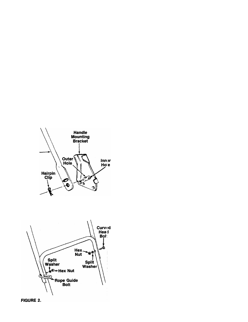
AHACHING THE UPPER HANDLE (Hardware B)
1. Place the upper handle in position over the lower
handle. The blade control handle (attached to the
upper handle) must be facing up.
NOTE: The right hand side of the handle will be secured
with the rope guide bolt. However, left handed operators
may assemble the rope guide bolt to the left side of the
handle for easier starting by following steps 2 and 3 and
reversing the left and right hand instructions.
2.
Secure the left hand side of upper handle using
the curved head bolt, split washer and hex nut as
------- shown in figure 2.
Insert the rope guide bolt through the right hand
side of upper and lower handle from the outside
in. Secure with split washer and hex nut, finger
tight only at this time.
3.