Danger, Tines, Warning – Troy-Bilt PRO LINE 645AMBRONCO User Manual
Page 21
Attention! The text in this document has been recognized automatically. To view the original document, you can use the "Original mode".
Sections: Maintenance
n
WARNING
Before inspecting, cieaning or servicing the unit, shut off engine, wait for aii
parts to come to a compiete stop, disconnect spark piug wire and move wire away from spark
piug. Faiiure to foiiow these instructions can resuit in serious personai in|ury or
property damage.
t
n'
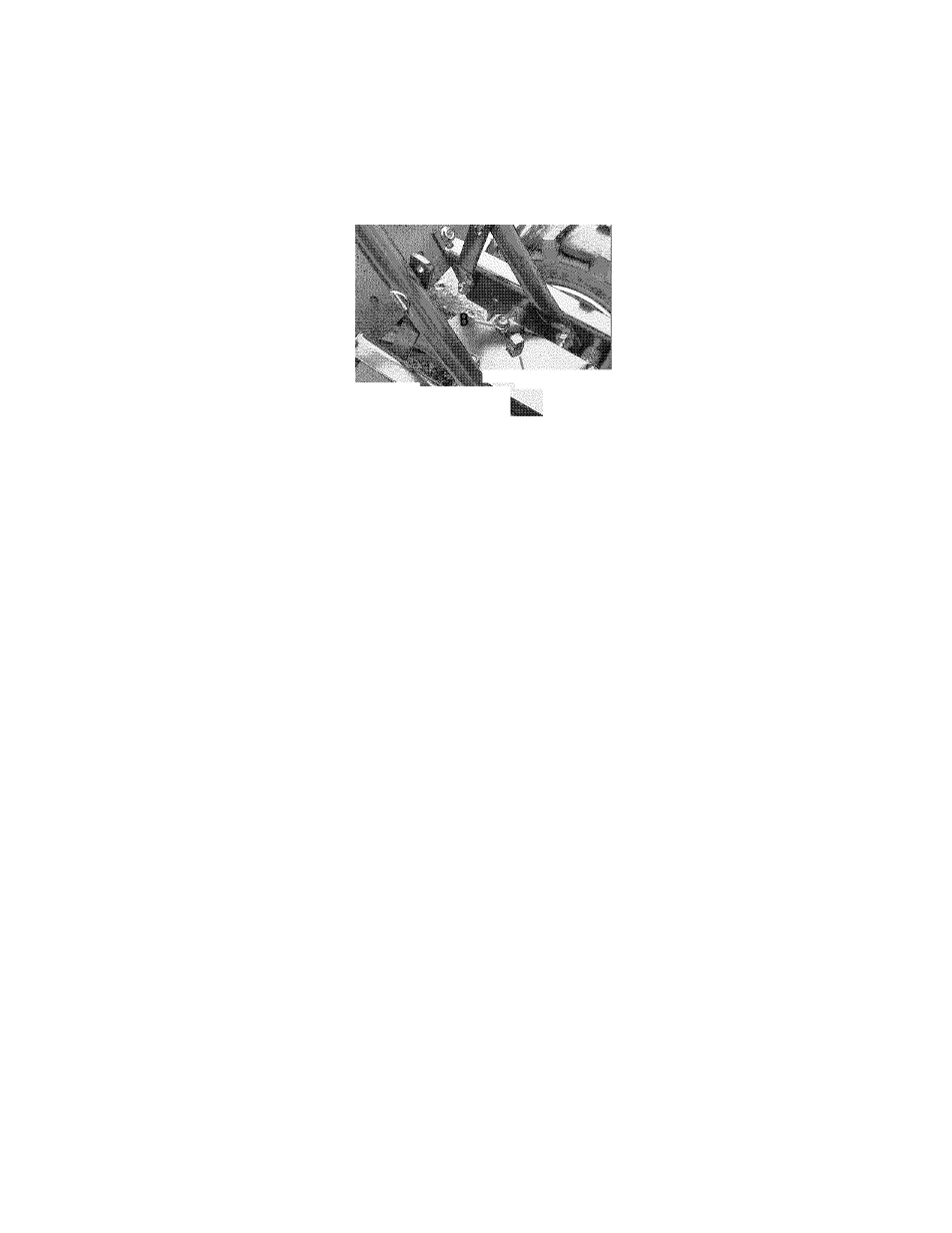
B. To Drain the Transmission Gear Oii:
DANGER
Gasoline is highly flammable
and its vapors explosive. Fol
low these safety practices to
prevent injury or property
damage from fire or explosion.
•
Allow the engine and
muffler
to
cool
before
draining the tiller’s gasoline
tank.
• Do not allow open flames,
sparks, matches or smoking
in the area.
• Wipe away spills and push
tiller away from spilled fuel.
• Use only an approved fuel
container and store it safely
out of the reach of children.
• Do not store gasoline where
its vapors could reach an
open flame or spark, or
where ignition sources are
present (such as hot water
and space heaters, furnaces,
clothes
dryers,
stoves,
electric motors, etc.)
The transmission gear oii does not need
to be changed uniess it has been contam
inated with dirt, sand or metai particies.
1. Drain gasoiine from the fuei tank or
run the engine untii the fuei tank is empty.
See “DANGER” statement above.
2. Drain the oii from the engine.
3. Remove the four screws (B, Figure 5-2)
and washers from the transmission cover
and remove the cover and gasket.
4. Remove the ieft-side wheei.
5. Tiit the ieft-side wheei shaft into a
drain pan and aiiow the gear oii to drain
through the top of the transmission.
6
.
After draining oii, reinstaii the wheei,
instaii a new gasket (do not reuse oid
gasket) and screw on transmission cover.
7. Refiii transmission using GL-4 gear oii
(SAE 85W-140orSAE140).
8. Refiii the engine with motor oii and
repienish the fuei tank with gasoiine.
Figure 5-2: Remove all fill plug (A) to cheek
gear oil level and to add gear oil. Remove
four cover screws (B) to drain gear oil.
TINES
The tines wear with use and they shouid
be inspected at the beginning of each
tiiiing season and after every 30 operating
hours. The tines can be repiaced individ-
uaiiy or as a compiete set. Refer to the
Parts List Section of this manuai for tine
identification information.
^ WARNING
This is a CRT (counter-rotating
tine) tiller and its tines must
be mounted in the direction
shown
in
Figure
5-3.
If
mounted with curves in the
opposite direction, tiller will
dig poorly and be more likely
to run backward.
Failure to comply could result
in personal injury or property
damage.
NOTE: You must first remove the tiiier
hood before removing either a singie tine
hoider or individuai tines. Remove the
two screws at the front of the hood and
the two screws at the rear of the hood
and iift off the hood. Be sure to repiace
the hood secureiy after changing a tine or
tine hoiders.
A. Tine Inspection:
With use, the tines wiii become shorter,
narrower and pointed. Badiy worn tines
wiii resuit in a ioss of tiiiing depth and
reduced effectiveness in generai, and
specificaiiy when chopping up and
turning under organic matter.
B. Removing and Installing
Tine Assemblies
1. Use a 9/16“ socket, 6“ extension, a
ratchet, and a 9/16“ box end wrench to
ioosen the nut (A, Figure 5-3) and screw
(B) that secure the tine hoider to the tine
shaft.
2. Use a rubber maiiet to tap the tine
hoider ioose. Siide tine assembiy off.
3. Repeat Steps 1 and 2 above to remove
the other tine assembiy.
4. Instaiiing the tine assembiy is simpiy
the reverse of its removai. First be sure
to remove any rust, uneven spots or burrs
from the tine shaft using fine sandpaper.
Then grease the tine shaft before rein-
staiiing the tine assembiies. Be sure aii
the cutting edges face so they wiii enter
the soii first when the tiiier is moving
forward- this means the cutting edge on
the top of each tine faces toward the
operator position. Tighten hardware.
C. Removing and Installing
Individual Tines
1. Use two 9/16“ box end wrenches to
remove the two screws (C, Figure 5-3)
and nuts (D) that secure the tine to its
tine hoider.
NOTE: If the nuts are rusted, apply pene
trating oil, then loosen the hardware.
2. When installing individual tines, do so
in the reverse order from which they were
removed. The two sets of inboardtlms
are installed so one set faces toward the
transmission and the other faces away
from it. The single outboardtlm set
faces toward the transmission housing.
Also be sure the cutting edge at the top
of each tine faces toward the operator
position. (See Figure 5-3.)
21