Wiring diagram – Troy-Bilt 13105 User Manual
Page 25
Attention! The text in this document has been recognized automatically. To view the original document, you can use the "Original mode".
S/N 13123130101—13123139999
13104120101—13104129999
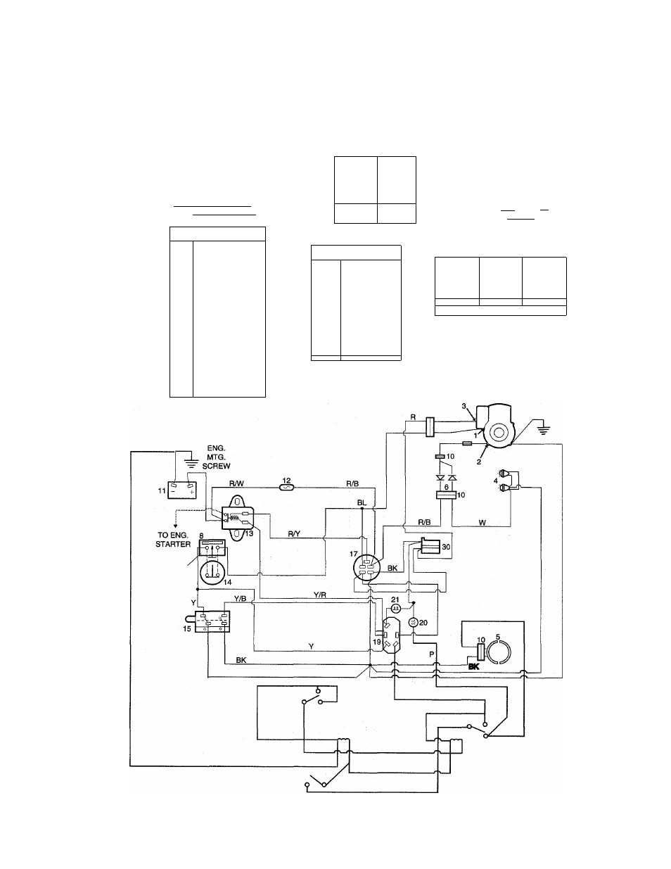
MODELS 13123 & 13104
WIRING DIAGRAM
Contact
located Inside
Connector
Body
BRAKE SWITCH
4-TERMINAL
SEAT
SWITCH
№
NORMAL DEPRESSED
V_______ TERMINAL VIEW y
©
N
0
NORMALLY
^ CLOSED
SEAT
DEPRESSED
ATTACHMENT
DRIVE SWITCH
i n
<5>
QFF
■)(!1
ON
REAR VIEW
---------
ITEM CODE
1
Magneto
2
Wternator
3
Fuel Solenoid
4
Headlights
5
Attachment Clutch
6
Diode Assembly
7
Starter
8
Seat Plug with Switch
10
Connector
11
Battery
12
Fuse
13
start Solenoid
15
Brake Switch
17
Key Switch
19
Attachment Switch
20
Attachment Light
21
Start light
30
Accessory Plug
WIRE COLOR CODE
BK
Black
BL
Blue
P
Purple
R
Red
W
White
Y
Yellow
n m
Red/White
R/B
Red/Black
RA"
Red/Yellow
m
Yellow/Red
W/B
White/Black
Y/B
Yellow/Black
IGNITION SWITCH
[Mli j ( m P^ b I \LC_Slly ( m P^H b ) OFF______ ___ BUN____ START ^ REAR VIEW ) BK BK 25
\Ll=y