Maintenance – Ariens Sno-Thro PM-32-77 User Manual
Page 6
Attention! The text in this document has been recognized automatically. To view the original document, you can use the "Original mode".
MAINTENANCE
BELT REPLACEMENT
CAUTION:
SINCE REPLACING THE BELTS WILL INVOLVE TURNING
THE ENGINE OVER WITH THE STARTER, THE SPARK
PLUG WIRE MUST BE DISCONNECTED DURING THIS
PROCEDURE.
The drive belt and the attachment drive belt are both ac
cessible by tipping apart the blower housing and tractor as
follows;
1. Remove the nut and washer holding the worm clevis on
the bracket. Remove the chute crank by sliding it back in
the bracket and out of the way.
2. Remove the two flanged whiziock screws securing the belt
guard to the tractor. Remove the belt guard.
3. Remove the top cap screws and loosen the lower cap screws
on each side that secures the blower housing to the frame.
As the blower housing and tractor are tipped apart, roll
the belt off the engine sheave between the sheave and belt
finger. This can be easily done by pulling the recoil
starter rope to rotate the engine sheave. With the belt dis
connected, the blower housing may then be tipped from
the frame.
REPLACEMENT OF TRACTION DRIVE BELT
With the blower and tractor tipped apart, spring the idler
from the drive belt and remove from around the lower sheave
and engine sheave. Install the new belt on the engine sheave
and lower sheave. Then spring the idle back into position on
the outside of the drive belt.
With the belts in position and the idler in place, check the
belt alignment. The engine sheave and the tractor sheave
must align with one another. If the sheaves are not properly
aligned, loosen the setscrews on the engine sheave and align
the sheaves. Retighten the setscrews.
BLOWER CLUTCH ADJUSTMENT
The blower clutch is adjusted by connecting the spring on
the clutch rod into the proper link on the clutch handle chain.
Properly adjusted, the spring should be slightly extended with
the clutch handle down. This should occur without the
attachment activator lever touching the hub. If the activator
lever touches the hub, the blower belt idler pulley must be ad
justed in the idler arm. Loosen the cap screw on the idler
and move the idler IN TOWARD the belt. Readjust the spring
in the chain for proper action.
o
TRACTION IDLER
BLOWER CLUTCH ROD
HUB
TRACTION CLUTCH ROD .
M\
ACTIVATOR LEVER ^ ^
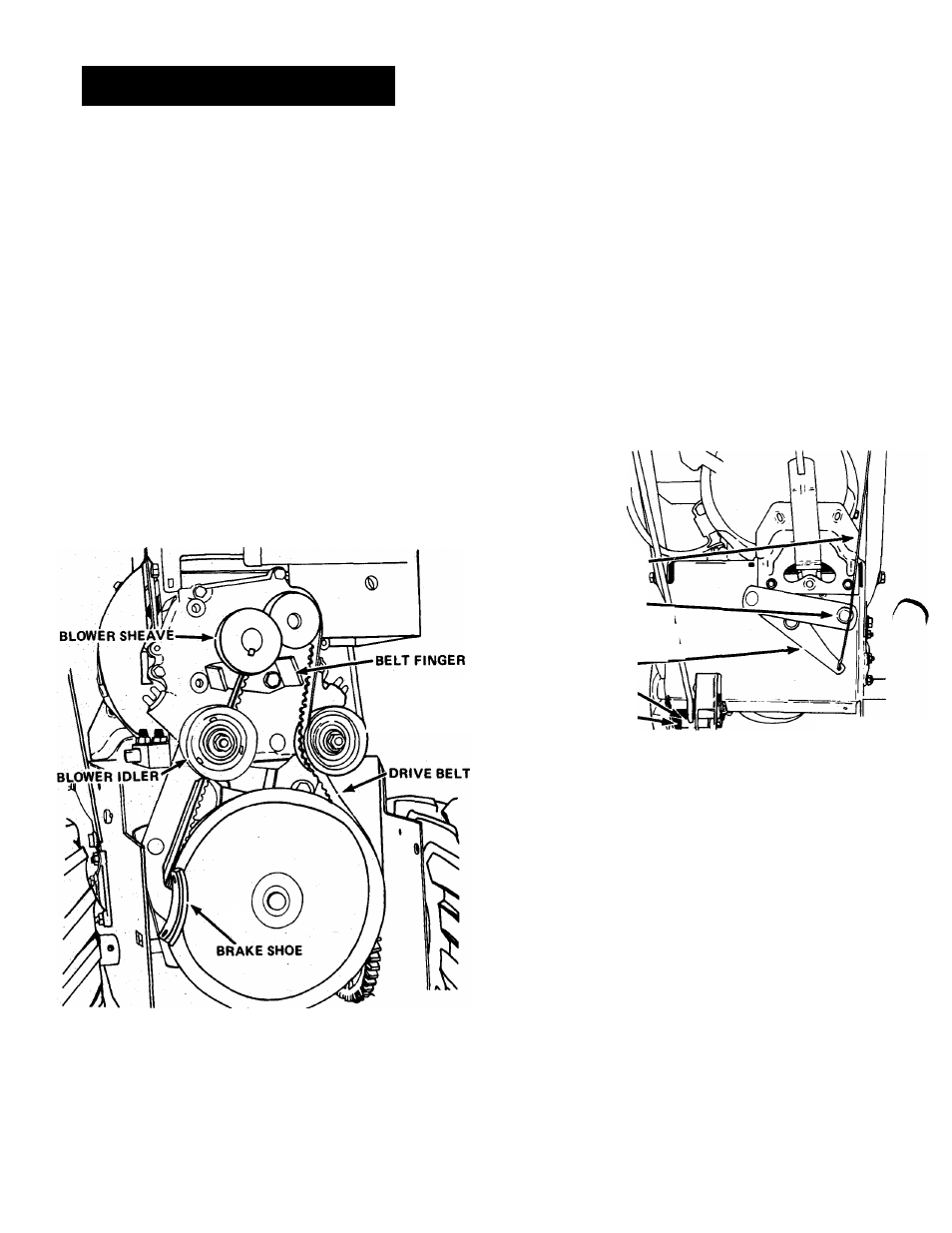
REPLACEMENT OF THE BLOWER DRIVE BELT
The blower drive belt remains on the sheave on the blower
housing. Place the new belt on the sheave. Hold it in position
On the sheave as the blower is tipped into position on the
tractor. Be sure the brake shoe seats on the belt as the units
are tipped together. Once assembled, roll the blower belt on to
the engine sheave and position the idler on the outside of
the belt.
ROD ADAPTOR
ALLEN SCREW
FIGURE 4
DRIVE DISC ADJUSTMENT
The only adjustment for the drive disc is made by adjusting
the length of the traction clutch rod. With the clutch handle
in the full upright position and the clutch bracket down
against the stop, tighten the alien screw in the rod adapter.
To check the adjustment, push the Sno-Thro with the clutch
handle up; it should roll freely. While pushing the Sno-Thro,
slowly lower the clutch handle. The wheels should start to
drag with the clutch handle approximately halfway down to
the handlebar grip when properly set. If necessary, adjust
the clutch rod in the rod adapter to secure this adjustment.
NOTE; The hex nut on the clutch link just above the spring
on the clutch linkage is NOT an adjustment. This nut should
be tightened just enough to hold the spring snug and prevent
the spring from rattling when traction clutch is released.
REPLACEMENT OF FRICTION WHEEL
1. Tip the machine up on the blower housing and brace
securely. Remove two cap screws at back of frame securing
the bottom cover and loosen two cap screws at front
frame sides and remove the cover.
-
6
-
2. Remove the four whiziock nuts holding the bearing flange
on the right hand side of the frame. Remove the bearing
flange and carriage bolts.