White Rodgers 668-430 User Manual
Page 2
Attention! The text in this document has been recognized automatically. To view the original document, you can use the "Original mode".
B. SAFETY TIMING:
1. Let the burner run for about 5 minutes. Then remove one
of Flame Detector leads from the “F” terminals. After a
time period corresponding to the safety timing has
elapsed, the control should lock out on safety, stopping
the burner and causing the red Safety Reset Indicator
Light to glovi/.
2.
Open the line switch.
3. Replace Flame Detector lead removed in step 1.
4. Wait about 3 minutes. Then operate the manual reset
button on top of control.
C. HIGH LIMIT AND THERMOSTAT CHECK:
1. Close the line switch to start the burner.
2.
Lower the setting of the high limit control to its lowest
setting. This should stop the burner, unless furnace or
boiler temperature is below the minimum setting of the
high limit.
3. Return high limit control to its proper setting. Burner
should restart.
4. With the burner running, turn thermostat to its lowest
setting. This should stop the burner, unless actual room
temperature is below the lowest setting of the thermo
stat. (Note: On systems supplying domestic hot water,
burner will continue to run if low limit control is not
satisfied.)
5. Return thermostat to its proper setting.
D. FLAME DETECTOR CHECK: (This test is not required if
the control performs as described in test A.)
If the burner starts but the control locks out (stopping the
burner), check the flame detector as follows:
1. Open the line switch.
2. Connect one end of a wire jumper to, one of the "F”
terminals.
3.
Start the burner by closing the line switch. As soon as
flame has been established, connect other end of the
wire jumper to the other “F” terminal. WARNING: The
control provides no safety protection with this jumper
installed. Do NOT leave burner in this condition except
for making this check.
If the control still locks out with the jumper installed,
the control should be replaced. If the control does not
lock out, however, check the operation of the 956 flame
detector as follows:
4. If safety lockout problem Is of an occasional nature, the
following additional check may be made to Insure that
flame detector location Is not a marginal one:
(a) Disconnect flame detector leads from “F” terminals.
D. FLAME DETECTOR CHECK (Continued):
Possible Cause of
Trouble
Correction
Open circuit in
Cell
Replace Cell (or Cell Assembly) of
956 Flame Detector. Do not disturb
position of bracket or socket assembly.
Flame detector im
properly positioned.
Locate flame detector according to
the burner manufacturer's speci
fications.
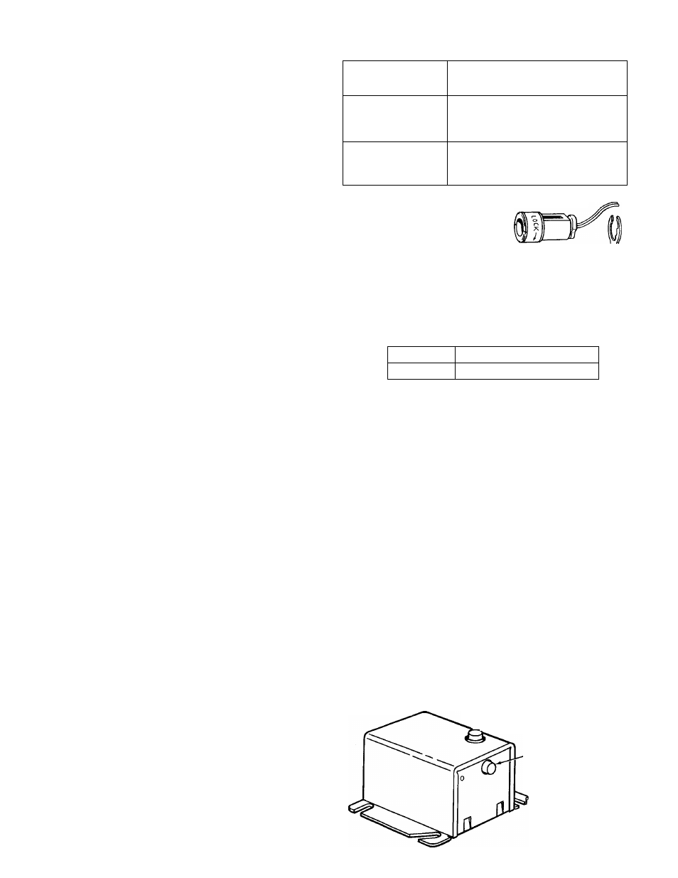
TYPE 956 FLAME DETECTORS
OLD STYLE
new
STYLE
D S
j
SOCKET
ASSEMBLY
CELL ASSEMBLY
Rotate Cell Assembly counterclock
wise to remove it. To replace it,
insert end through notched opening
in bracket and rotate ciockwise.
NOTE: if bracket is ever removed
from burner, Ceii Assembiy wiii
bracket
not fit if bracket is reinstaiied
backwards.
PART No. OF REPLACEMENT PARTS
63-0485
Cell only (Old Style)
63-2006
Cell Assembly (New Style)
(b) Attach a jumper wire to one “F” terminal. Start burn
er. Then immediately connect jumper wire to the
other “F" terminal. Burner should continue to run.
(c) With burner running, attach flame detector leads to
an accurate ohmmeter. Reading of ohmmeter should
be below 1000 ohms, and preferably as low as 500
ohms.
(NOTE: If indicator of ohmmeter remains steady,
readings up to 2000 ohms should also be acceptable.
Generally, though, the lower the reading, the better
the application, and less likely the chance of a varia
tion in the burner flame causing a safety lock-out.)
(d) If resistance of flame detector is over 1000 ohms, it
may not be able to see the burner flame properly.
Check alignment of the flame detector through the
hole in the static pressure disc. Clean this hole if it
is blocked by foreign matter. Check for broken “F”
wires.
(e) If flame detector alignment is good but resistance
is still high, readjustment of burner flame and/or
nozzle replacement may be necessary (according to
burner manufacturer’s instructions).
(f) WARNING: Be sure to remove wire jumper after
finishing this flame detector check.
OPERATION OF MANUAL LOCKOUT
LEVER ON SAFETY SWITCH
To insure shutdown of burner during servicing, push in on
Safety Reset Indicator Light to trip Safety Switch, causing the
Reset Button to pop out and Indicator Light to glow.
CAUTION: ELECTRIC SHOCK IS STILL A POSSIBILITY.
Although lockout of safety switch will interrupt
the entire line voltage circuit to burner, terminal
No. 1 (power supply) will remain "Hot".
When burner servicing is finished, simply push in on Reset
Button to reset the Safety Switch,
RESET BUTTON
/
SAFETY RESET INDICATOR
LIGHT AND MANUAL
LOCKOUT BUTTON