White Rodgers 668-430 User Manual
White-rodgers, Oil burner control
Attention! The text in this document has been recognized automatically. To view the original document, you can use the "Original mode".
WHITE-RODGERS
TYPE 668-430
Intermittent Ignition* — Non Recycling
OIL BURNER CONTROL
With Safety Reset Indicator Light
(For use with Type 956 Flame Detector,
on 2-wire or 3-wire Series 10 systems)
This type 668 Oil Burner Control provides safe operation
of'oil burners on heating plants where ignition during the
entire burner cycle is desired. It may be used with either
a 2-wire or a 3-wire Series 10 thermostat.
This 668 control is equipped with a red Safety Reset Indi-
--------------------INSTALLATION--------- ------ ----
cater Light
which glows whenever the control locks out on
safety to stop the burner. The 668 is for use with the 956
Flame Detector.
'Formerly called constant ignition.
SPECIFICATIONS
The proper Location and Mounting of the primary oil burner
control panel on the burner and the flame detector with
respect to the oil flame shall be determined by the furnace,
boiler, or burner manufacturer.
Room Thermostat: Set dial of adjustable heater at .4A. If
Time Delay Fan Switch is used, set dial at .5A (for typical
Fan Switch current of .15A.)
Time Delay Fan Switch {.15A Max. at 25v): If used, connect
to Fi-B terminals.
Safety Timing: 45 seconds.
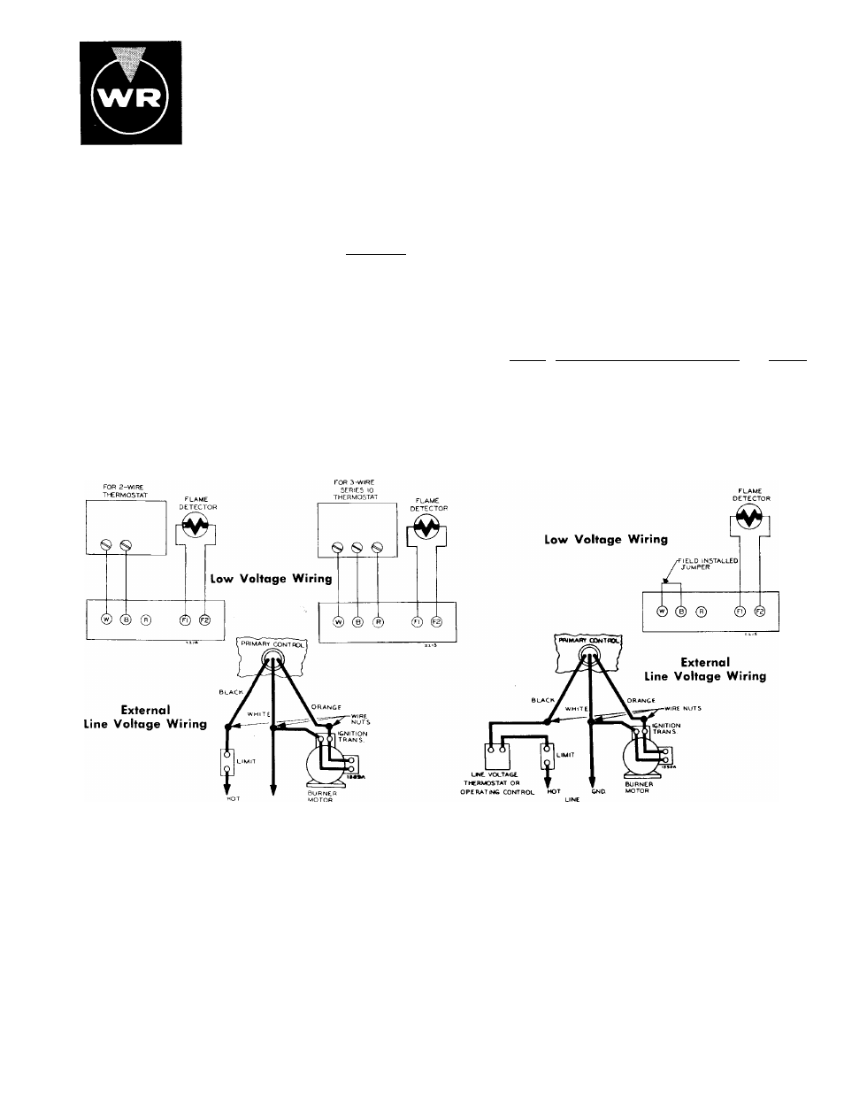
WIRING------- ------ -------- ----------------------- —-----------
If this control, supplied as part of a furnace, boiler or burner,
is wired to the equipment or if the manufacturer of such
equipment provides instructions for wiring this control, then
follow his recommendations. If no special wiring instruc
tions are given, then follow the electrical connections shown.
USING 668-430 TO REPLACE LOW VOLTAGE
PRIMARY CONTROLS (SUCH AS TYPES 668-1 TO -99)
For more complicated systems, especially for hot water
heating, consult the manufacturer of the heating plant or
write to White-Rodgers giving full details of the desired
sequence of control operation.
USING 668-430 TO REPLACE LINE VOLTAGE
PRIMARY CONTROLS (SUCH AS TYPES 6L68-1 TO -99)
TESTING
The following control checks should be made after each
installation to insure that the controls are correctly wired
and functioning properly.
1. Open the main line switch.
2. Adjust thermostat or operating control to call for heat.
3. Operate the manual reset button on top of control.
4.
Make certain that high limit control is set at the correct
temperature.
5.
Open the hand valve in the oil line. The system is now
ready for the following tests.
A. NORMAL CYCLE:
Close the line switch. The burner should start and con
tinue to run normally. (If burner starts, establishing
flame, but then locks out on safety, make “Flame Detec
tor Check” at this time.
(TESTING CONTINUED ON NEXT PAGE)
Is
IsMisRSDN <
WHITE-RODGERS DIVISION
EMERSON ELECTRIC CO.
9797 REAVIS ROAD
ST. LOUIS, MISSOURI 63123
Printed in U.S.A.
PART No. 37-2649-A
Replaces 37-2649