Component testing procedures â warning – Amana Pi143415N User Manual
Page 2
Attention! The text in this document has been recognized automatically. To view the original document, you can use the "Original mode".
Component Testing Procedures
 WARNING
To avoid risk of electrical shock, personal injury, or death, disconnect power to oven before servicing, unless
testing requires it.________________ ______________________________
Illustration
Component
Test Procedure
_______________ Results ______________
Indicates continuity with bulb screwed in.
If not replace._________________________
31823701
Oven light socket
Test continuity of receptacle
terminals.
31722801
Oven indicator light
and
Surface indicator light
Remove one lead from switch
terminal and measure resistance
across terminals.
Measure voltage at indicator light.
Switch closed; 0 il
Switch open; Infinite resistance
If voltage is present and light does not
operate. Replace light.
If no voltage is present at indicator light
check wiring._________________________
301491
Rocker switch
Measure continuity of switch
positions;
Closed
Open
Ccmtinuity, if not replace.
Infinite, if not replace.
31734602—1500
W
31734606-^600 W
Coil surface elements
6" and 8"
Test continuity of terminals.
Continuity, if not replace.
31730101
Coil surface terminal
block
Remove element and turn surface
element on and test for voltage at
terminal block.
240 VAC
31794701-1200
W
31794601-1500
W
31794501-2000
W
31794801-2500 W
Ribbon radiant
elements
Remove one wire lead from element
and measure resistance of the
element.
Continuity, if not replace.
1200W: 45 to 51 n
1500W: 36 to 41
Cl
2000W:
27 to 31 Q
2500W: 21 to 25 n
31846201
Ribbon surface
thermal limiter/hot
light switch
Turn surface element on and test for
voltage. See wiring diagram and
schematic.
1a-2a 240 VAC
1b-2b 120 VAC
Disconnect leads and measure
resistance on the foNoviring:
1a-2a room temperature-continuity
1b-2b room temperature-infinite
240 VAC
uwb
A
EtotirovM
q.n
TTl
V‘
■u
a
Th«mwO>Oisc (TOO)
n n
to la
r
Î
trxr
Might
059552
Bake element
Disconnect wire ieads to element and
measure resistance of terminals.
Measure voltage at bake element.
Continuity, approximately 23 Q,
if not replace.
240 VAC, see wiring diagram for terminal
identification.
If no voltage is present at bake element
check wiring.__________________________
061732
Broil element
Disconnect wire leads to element and
measure resistance of terminals.
Measure voltage at broil element.
Continuity, approximately 19 il,
if not replace.
240 VAC, see wiring diagram for terminal
identification.
If no voltage is present at broil element
check wiring.
314907
Oven temperature
sensor
Measure resistance.
Approximately 1100 o at room
temperature 75° F.____________
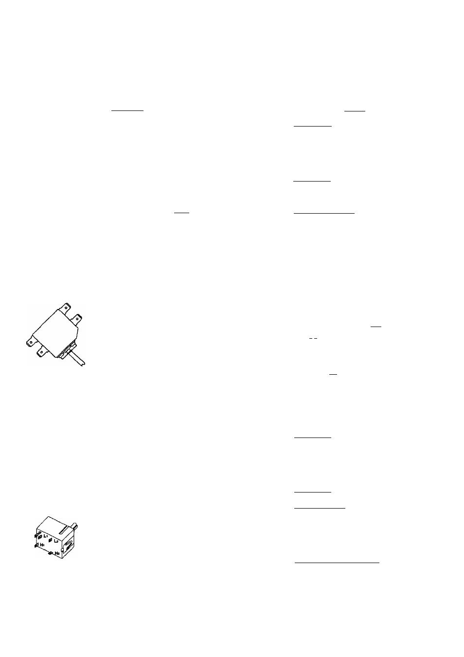
31891202
Infinite switch
Remove wiring from terminals HI and
H2. Connect Volt ohms meter to
HI and H2.
Measure the following for voltages at
LO, MED, HI;
HI to H2
Time On
LO
5%
MED (4-5)
50%
HI
100%
Time Off
95%
50%
0
%
240 VAC, if not replace switch.
RT2320003 Rev. 9
April 1999