How to set up your snow thrower, To assemble snow chute, To install the upper handle and crank assembly – Sears 536.886331 User Manual
Page 8: Assembly
Attention! The text in this document has been recognized automatically. To view the original document, you can use the "Original mode".
ASSEMBLY
•
Assemble the snow chute.
•
Roll snow thrower oif the skid by pulling on the handle.
•
Properly dispose of discarded packaging.
HOW TO SET UP YOUR SNOW
THROWER
Your snow thrower is equipped with height adjust skids
(See FIG. 2)
on the outside of the auger housing. To adjust
the skid height, see To Adjust Skid Height paragraph in the
Service & Adjustments section of this manual.
(See Fig
ure 1 page 20).
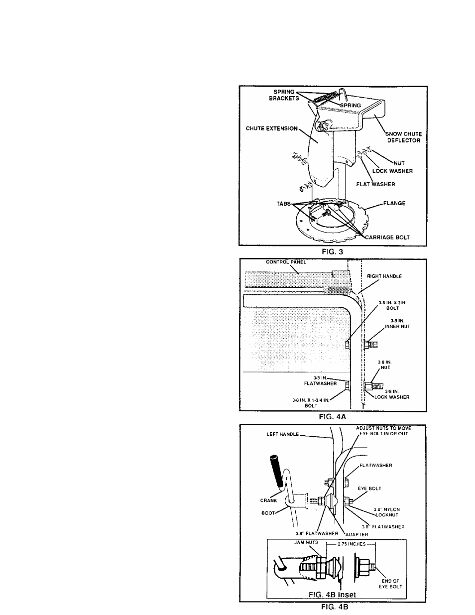
TO ASSEMBLE SNOW CHUTE
•
Remove three carriage bolts, flat washers, lock wash
ers and nuts from snow chute flange,
•
Position snow chute on snow chute flange and align
the three holes in the snow chute with tabs on snow
chute flange.
•
Replace carriage bolts from inside of chute as shown
in FIG. 3, flat washers, lock washers, nuts and tig nien
•
Hook remote chute return spring supplied tivough
both spring bracket as on deflector and chute exten
sion.
TO INSTALL THE UPPER HANDLE
AND CRANK ASSEMBLY
•
On the right side of the handle, install and secure the
following parts
(found
in
parts
box) in the lower
handle hole as shown in FIG. 4A;
1 - 3/8" X 1 -3/4" bolt
1 • 3/8" flat washers
1 - 3/8" lock washer
1 - 3/8" nut
•
Remove the 3/8" nylon locknut and flat washer from
the eye bolt assembly
(on the chute crank assem
bly).
Check to make sure the two 3/8" jam nuts are
tight.Thejamnulsshouldbe2.75
inchestromtheend
of the eye bolt
(FIG. 4B inset).
•
Install eye bolt through lower hole on the left hand side
of the handle (See FIG. 4B)
•
Install the 3/8" flatwasher and the 3/8" nylon locknut
loosely on the eye bolt as shown in FIG. 4B
•
Remove the plastic bag from chute crank assembly
Remove the plastic cap, colter pin and washer from
the wormed end of the auger assembly (See FIG. 5
page 9)
•
Rotate the notched section of the discharge chute
toward the crank-adjusting rod (See FIG. 5 page 9)
•
Install the wormed end of the crank through the hole
in the adjusting rod and secure the end with the flat
washer and cotter pin, as shown in FIG. 5 page 9