Assembly – Sears 831.159231 User Manual
Page 4
Attention! The text in this document has been recognized automatically. To view the original document, you can use the "Original mode".
ASSEMBLY
Place all parts in a cleared area and remove the packing materials. Do not dispose of the packing
materials until assembly is completed. Read all steps carefully before beginning. See the PART f.D.
CHART accompanying this manual for a drawing of each small part used In assembly and for a
list of the tools heeded. The assistance of a second person is recommended.
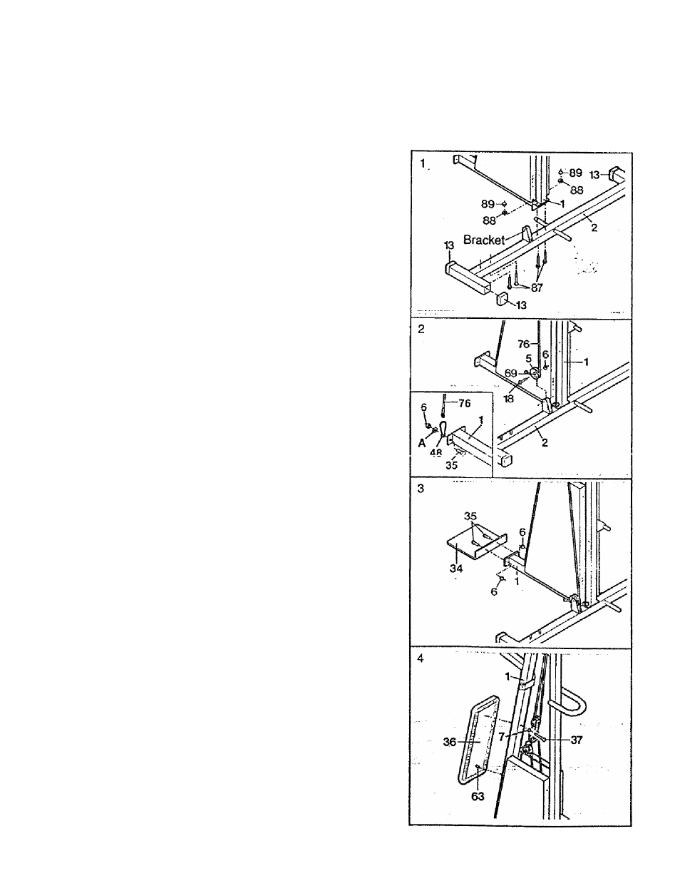
1. Press the four 2" x 2" Outer Caps (13) onto the
Stabilizer (2). Turn the Stabilizer so the indicated
bracket is on top. Insert the four 3/8" x 2 1/2" Carriage
Bolts (87) up through the Stabilizer as shown.
Place the Frame (1) over the two indicated 3/8" x
21/2" Carriage Bolts (87) as shown. Finger tighten
two 3/8" Nuts (89) with 3/8" Lock Washers (88) onto
the Carriage Bolts.
2. Remove the 3/8" x 3/4" Bolt (35), the Cable Hook (48),
the extra washer (A), and the 3/8" Nylock Nut (6)
which secure the Lower Cable (76) to the Frame (1)
as shown in the inset. Do not release the Cable until
completing this assembly step. The 3/8" x 3/4" Bolt
(35) and the 3/8" Nylock Nut (6) will be used in
' assembly step 3 below. The Cable Hook will be used
later. The extra washer should be discarded.
in P PillliiX/
-------- , -----------
\A!mr\
+K
q
Centpf a Pulley Sleeve (59)
Lower Cable (76) under the Pulley. Attach the Pulley
to the Stabilizer (2) with a 3/8“ x 1 3/4“ Bolt (18) and
3/8" Nylock Nut (6) as shown. Do not overtighten the
Nut. The Pulley should turn freely.
3. Attach the Foot Plate (34) to the Frame (1) with the
two 3/8" x 3/4" Bolts (35) and two 3/8“ Nylock Nuts (6).
Press the Backrest Post (63) at the lower end of the
Backrest (36) into the Frame (1) as shown. Attach the
upper end of the Backrest to the Frame with the 1/4" x
2 1/2" Bolt (37) and a 1/4" Lock Washer (7).