Wiring instructions – Sears 279787 User Manual
Page 3
Attention! The text in this document has been recognized automatically. To view the original document, you can use the "Original mode".
3,
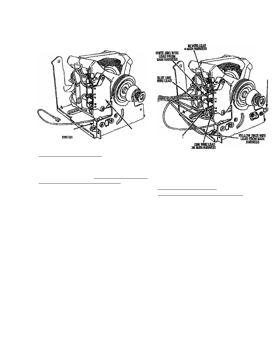
Position motor as shown in Figure Z Note the location
of the motor switch. Secure motor to bracket with the
origirtai motor damps.
13, Connect the black
wire toad onto the i /e” terminal
marked “6" on the motor sw'itch. Se$ Figure 3.
BROKEM
кспЕьшток
ОРЖМОТОЙ
SWiïCH
RGi/R^2
S.
WIRING INSTRUCTIONS
NOTE: Read and follow instmoUons carefully- H the
unit you are replacing the motor on has the option
which included the momentary switches for the drum,
proceed to section title WIRING ti^STRlfCTtONSTr-
MOMENTARY
SWITCH
APPLlCATIONr
otherwise,
proceed to step 4.
4.
Connect the blue (4M) wire lead from the broken belt
switch to the vacant terminal located on the back of
the overload protector of the motor switch. See
Figure S
Connect the red (1M) wire lead to tie 4F terminal
marked "1" on the motor switch. See Figure 3.
6. Conned the red {2Mi} wire lead to the 4i" terminal
marked *‘2" on the motor switch. See Figure S
7. Connect the yellow (BK2) wire lead to Ihe vacant
terminal on the broken belt switch. See Figure 3.
8.
To connect the black (6M) wire lead and the white
(5lui) wire lead to the motor switch, you must replace
the ^ A" female terminals with the'' /e" insulated female
terminals Included wUh the replacement motor.
9„ Cut the femaii terminal from the black (6M) and
white (5MJ wire leads as close to the terminal as
possible with wire cutlers.
10, Strip wires back approximately V
11
,
With barrel crimpers,
crimp
Va"
insulated
female
terminals, Included with motor, onto the vráe leads.
NOTE;
Make
sure terminals
are
crimped
securely
trt place,
12, Connect the white {5M) wire lead onto tho ’ k" terminal
marked "5" on the motor switch. See Figure 3.
GROtmD
WIRE {GREE
....... vmi
IfADFROMMAiH
KAR№S£ RS)
FRf'
mms
14. Reconnect ground wire to motor. See Figure 3.
15- All wire lead connections are complete at this point,
you can now reinstall the motor and bracket assembiy
Into
the
unit.
WIRING INSTRUCTIONS-^
MOMENTARY SWITCH APPLICATION
1.
Connect the blue (4M) wire lead from the broken belt
switch to the vacant terminal located on the back of
the overfoad protector of the molor switch. See
Figure 4.
2.
Connect the red wire lead to the V-i" terminal
marked "t" on the motor switch. See Figure 4.
3.
Conned the red (2M) wire lead to the 'A” terminal
marked “2" on the motor switch. See Figure 4,
4.
Conned the yellow (BK2) wire lead to the vacant
terminal on the broken belt switch. See Figure 4.
,5, To conned the purple {3M} wire lead and the white
(5fvt) wire lead to the motor switch, you must replace
the 1 A” female terminal with the < h' insulated terminals
included with the repiacement motor.
■
Cut the
WT'
female terminaJ from the purple f3M)
and
white (5M} wire leads as close to the terminal as
possible with wire cutters.
270738-A
„.-2-