Awarning, Sediment trap, Gas piping with flexible connector – Sears POWER MISER 153.335914 User Manual
Page 19: Gas piping with all black iron pipe to gas control, Installation instructions (cont’d), Gas piping
Attention! The text in this document has been recognized automatically. To view the original document, you can use the "Original mode".
Installation Instructions (cont’d)
Gas Piping
AWARNING
Make sure the gas supplied is the same type listed on the
model rating plate. The inlet gas pressure must not exceed
14 inches water column
'A
pound per square inch (3.5kPa)].
The minimum inlet gas pressure listed on the mo^l rating
plate is for the purpose of input adjustment
AWARNING
If the gas control valve is subjected to pressures ecceeding
'A
pound per square inch (3.5kPa), the dam^ to the gas con
trol valw could result in a fire or explosion ^m leaking gas.
AWARNING
If the main gas line shutoff serving all gas appliances is used,
also turn “oir' the gas at each appliance. Lem ^1 gas appli
ances shut off until & water heater installation is complete.
A gas line of sufficient size must be run to the water heater.
Consult the latest edition of National Fuel Gas Code ANSI
Z223.1, also referred to as NFPA54 and the gas company con
cerning pipe size.
There must be:
•A readily accessible manual shut off valve in the gas supply line
serving the water heater, and
•A drip leg (sediment trap) ahead of the gas control valve to help
prevent dirt and foreign materials from entering the gas control
valve.
•A flexible gas connector or a ground joint union between the
shutoff valve and control valve to permit servicing of the unit.
Be sure to check all the gas piping for leaks before lighting the
water heater. Use a soapy water solution, not a match or open
flame. Rinse off soapy solution and wipe dry.
Standard Modeb are for installation up to 3,300 feet above sea
level.
Hig;h Altitude Models are for installation from 3,300 to 5,500
feet above sea level.
If a standard model is installed above 3,300 feet or a high altitude
model is installed above 5,500 feet, the input rating must be
reduced at the rate of 4 percent for each 1,000 feet above sea level.
Contact your local Sears Service Center or gas utility for further
information.
AWARNING
The appliance and its gas connection must be leak tested
before placing the appliance in operation.
AWARNING
>
The appliance and its individual shutoff valve must be discon
nected from the gas supply piping system during any pressure
testing of the gas system at test pressures in excess of
VI
pound per square inch (3.5kPa).
>
The appliance must be isolated from the gas supply piping sys
tem by closing its individual manual shutoff valve during any
pressure testing of the gas supply piping system at test pres
sures equal or less than 1/2 pound per square inch (3.5kPa).
__________________AWARNING___________
Use pipe joint compound or teflon tape marked
resistant to the action of petroleum [Propane (LP.)]
as being
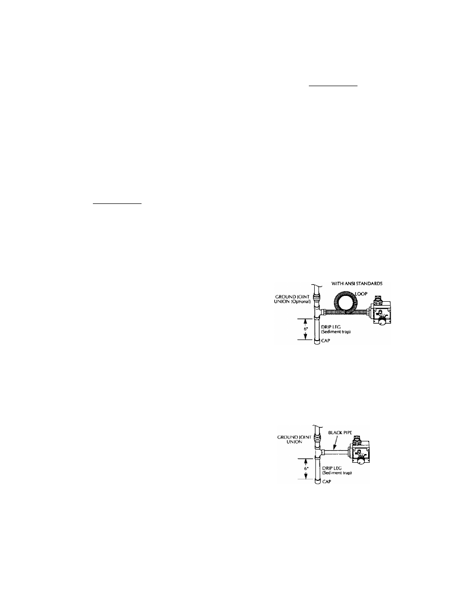
SEDIMENT TRAP
A sediment Crap shall be installed as close to the inlet of the
water heater as practical at the time of water heater installation.
The sediment trap shall be either a tee fitting with a capped nip
ple in the bottom oudei or other device recognized as an effec
tive sediment trap. If a tee fitting is used, it shall be installed in
conformance with one of the methods of installation shown
below.
Connecting the gas piping to the gas control valve of the water
heater can be accomplished by either of the two methods shown.
GAS PIPING WITH
FLEXIBLE CONNECTOR
I CAS SUPPLY PIPING
MANUAL
SHUTOFF
VALVE
FLEXIBLE CAS CONNECTOR
LABELED AS COMPLYING
CAS
CONTROL
VALVE
GAS PIPING WITH ALL BLACK IRON
PIPE TO GAS CONTROL
GAS SUPPLY PIPING
MANUAL
SHUTOFF
VALVE
CAS
CONTROL
VALVE
19
AWARNING
Contaminants in the gas lines may cause improper operation
of the gas control vaWe that may result in fire or explosion.
Before attaching the gas line be sure that all gas pipe is clean
on the inside. To trap any dirt or foreign material in the gas
supply line, a drip leg (sometimes called a sediment trap)
must be incorporated in the piping. The drip leg must be
readily accessible. Instsdl in accordance with the “Gas Pi|Mn^’
section. Refer to the latest edition of the National Fuel Gas
Code, ANSI Z223.1, also referred to as NFIV^ 54.