Sears 536.9183 User Manual
Page 5
Attention! The text in this document has been recognized automatically. To view the original document, you can use the "Original mode".
cable is loose and sags when lever is pushed all the way
down to last notch. To adjust cable;
A. Loosen bottom nut on power clutch cable (figure 4)
and tighten top nut until lever will reach top notch.
B. Loosen top nut and tighten bottom nut to remove
looseness from cable when lever is in bottom
notch.
5- Attach throttle control lever assembly (other end of
cable attached to left rear of engine) to control panel as
shown in figure 4 by:
A. Insert lever up through slot in left side of control
panel.
B. Attach with two No. 10 x Vi inch hex washer head
screws and two No. 10 locknuts. NOTE; Before
tightening screws and locknuts, check to make sure
that lever does not rub side of slot in control panel.
6, Attach impelter/auger drive control lever (other end of
cable is attached on right side of unit below gas tank) to
control panel as shown in figure 4 by:
A. Insert lever up through slot in right side of control
panel,
B. Attach with two No. 10 x Vi inch hex washer head
screws and two No. 10 locknuts. NOTE: Before
tightening screws and locknuts, check to make sure
that lever does not rub side of slot in control panel.
C. Attach impeller/auger drive control cable to handle
with a cable clamp.
D. Place a knob onto throttle and impeller/auger drive
control levers and tap firmly with a hammer until
knobs will not pull off. CAUTION: Knobs are made
of plastic and will break if hit too hard. A plastic or
rawhide hammer is recommended.
7. A power clutch cable is attached under belt cover in
front of engine. Cable should wrap around left side of engine
and under carburetor. Attach cable by:
A.
Remove top nut from threaded end of cable and
slide cable through slot in lower edge of control
panel.
B.
Push threaded end of cable up through hole in
control panel and replace, but do not tighten, top
nut.
C. Hook loop end of power clutch cable over pin on
■ power clutch lever (figure 4). NOTE: It may be
necessary
to loosen
bottom nut
on cable to
lengthen cable enough to hook over pin on clutch
handle.
D.
Tighten bottom nut on power clutch cable until
cable stop (figure 4) just clears top end of threaded
portion of cable. Tighten top nut to complete
assembly.
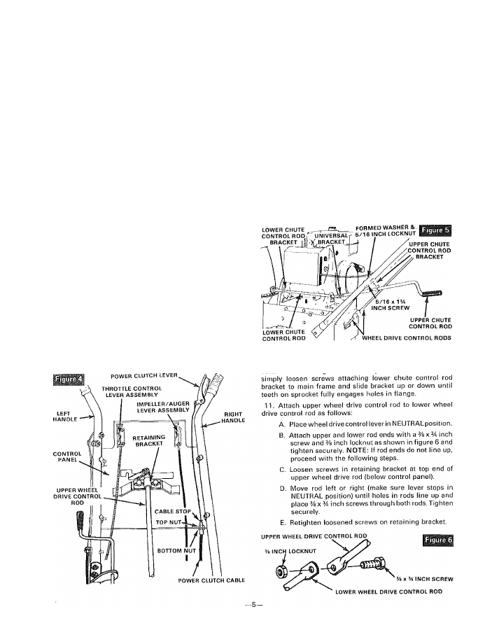
8. Attach upper chute control rod and upper chute control
rod bracket (mounted on rod) to bottom side of left handle
(figure 5) with two 5/16 x 1% inch hex head screws, two
5/16 inch locknuts, and two formed washers.
9. Remove the 1 inch screw and locknut from pivot block
(part of universal bracket) located on end of lower rod (figure
5). Insert lower end of upper rod onto pivot block in universal
bracket (figures) on lower chute control rod and secure with
the removed screw and locknut. CAUTION: Do not tighten
locknut
against
universal
bracket.
This
screw
and
nut
must be loose enough to allow universal to move freely.
10.
Check sprocket end of chute control rod to make sure
teeth on sprocket fully engages holes in flange around