Maintenance, A danger a, Caution – Sears 536.9183 User Manual
Page 10
Attention! The text in this document has been recognized automatically. To view the original document, you can use the "Original mode".
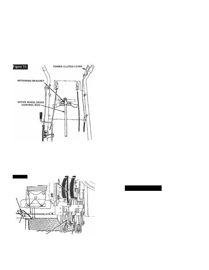
B. Leave wheel drive control lever in position where
neutral was obtained and release power cutch
lever. Shut off engine.
C, Loosen screws in retaining bracket (figure 15) at top
end of wheel drive control rod(under control panel),
D. Slide retaining bracket and rod left or right until
wheel drive control lever Is in proper neutral
position. Tighten screws in retaining bracket,
E, Start engine and check adjustment by moving lever
to each position, NOTE: Be sure to check to see that
NEUTRAL is property reached from both directions
{from reverse and from forward gear).
IMPELLER/AUGER CONTROL CABLE
ADJUSTMENT
If impeller/auger control should need adjustment because
impeller/auger will not engage or will not disengage, adjust
as follows:
1. Remove belt cover (figure 11).
Figure 16
IMPELLER/AUGER
CONTROL CABLE
SCREW
POWER CLUTCH CABLE
Ys
CLAMP
CABLE BRACKET
SELECTOR ARM
Va
INCH CLEARANCE
2.
Move impeller/auger control lever from OFF to
ENGAGE and check action of selector arm {figure 16). When
impeller/auger control lever is in ENGAGE position, pin
through selector arm should fully engage wheel drive arm
and impeller/auger drive arm. When lever is in OFF position,
pin through selector arm should engage wheel drive arm
only and clear impeller/auger drive arm by at least Vs inch.
To adjust to these positions;
A. Loosen screw that clamps impeller/auger control
cable to cable bracket (figure 16).
B. Move cable forward or backward in clamp to obtain
proper position mentioned above.
C. Reclamp cable by tightening loosened screw.
A DANGER A
Never attempt to manually stop auger from turning.
CARBURETOR ADJUSTMENT
HIGH SPEED and IDLE ADJUST NEEDLES are pre-set at the
factory and re-adjustment should notbe necessary. NOTE: If
you think the carburetor needs adjusting, contact your
nearest
SEARS
Service
Center
who
has
the
proper
equipment
and
experience
to
make
any
necessary
adjustments.
A
CAUTION
A
Never tamper with engine governor which isfactory
set for proper engine speed. Over-speeding engine
above factory high speed setting can be dangerous.
If you think the engine governed high speed needs
adjusting,
contact
your
nearest
SEARS
Service
Center
who
has
the
proper
equipment
and
experience to make any necessary adjustments.
Changing of engine governed speed will void engine
warranty.
SPARK PLUG ADJUSTMENT
Check the spark plug periodically and reset spark plug gap to
0.030 inch using a wire feeler gauge.
The condition of the spark plug may be determined by color.
A carbonized plug is black and burnt plugs are greyish in
color, whereas a normal functioning spark plug is brown. If a
new spark plug is required, refer to the Engine Repair Parts
section for proper replacement spark plug.
Before
installing
spark
plug,
coat
threads
lightly
with
graphite grease to insure easy removal.
MAINTENANCE
DRIVE BELT REPLACEMENT
The drive belts on this unit are of special construction and
should be replaced with original equipment belts available
from your nearest SEARS Store or Service Center,
To Replace Unit Drive Belt (belt nearest engine):
1. Remove belt cover (figure 11).
2.
Loosen screw holding left belt guide (figure 12) and
swing guide away from pulley. Retighten screw.
3. Loosen screw holding right belt guide (figure 12) and
swing guide away from pulley. Retighten screw.
4. Roll belt off engine pulley. NOTE: It will be necessary to
roll impeller/auger drive belt off engine pulley to allow unit
drive belt to be removed from engine pulley.
5.
Remove belt by threading up between large drive
pulleys.
6. Install new belt in reverse order.
—10-