Steps to install your water heater (continued), Time switch or off peak wiring, Warning – Sears 449.310411 User Manual
Page 8: Fig. 3e, Wiring, Schematic, Caution, Fig.3f, Water heater start-up
Attention! The text in this document has been recognized automatically. To view the original document, you can use the "Original mode".
STEPS TO INSTALL YOUR WATER HEATER (Continued)
TIME SWITCH OR OFF PEAK WIRING
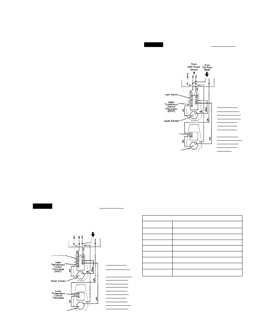
For TIME SWITCH or “OFF-PEAK” operation of the lower
element see either FIG. 3E or 3F wiring schematic.
CAUTION:
If you are going to wire the unit for either a
TIME SWITCH or “OFF-PEAK” operation, the black wire
from Terminal No. 4 of the limit switch must be disconnected
and replaced totally or disconnected and joined with a new
section of wire using a proper connector. BE SURE TO
FOLLOW ALL LOCAL AND NATIONAL CODES AND
ELECTRIC UTILITY REQUIREMENTS WHEN MAKING THE
CONNECTIONS.
Dual element water heaters are designed to allow only one
element to heat at a time, This method is called
non-simultaneous operation and is necessary to avoid
overloading wiring in the house per the National Electric
Code. Off-Peak wiring methods must ensure proper use of
the high limit control in at least one line to each element
and use the non-simultaneous feature.
----------------------- WARNING ----------------------------
IF YOU ARE NOT FAMILIAR WITH WIRING AND YOU
HAVE ANY DOUBTS, YOU SHOULD GET HELP FROM A
LICENSED ELECTRICIAN. IF YOU DO SOMETHING
WRONG, SEVERE BURN OR SHOCK HAZARDS CAN
RESULT.
* REPLACE THE JUNCTION BOX COVER after you have
made the wiring connections.
CAUTION:
DO STEP 7, PAGE 6 BEFORE TURNING ON
ELECTRICAL POWER TO THE WATER HEATER.
FIG. 3E
WIRING
SCHEMATIC
NON-SIMULTANEOUS
OPERATION
BOTTOM ELEMENT
ON SEPARATE TIME
SWITCH
Water Healer ^
Junciion Box
From
From
2<0V Powew Tima Clock
Source
Switch
♦
FOR MODEL NOS.
449.310310
449.310311
449.320310
449.320311
449.310410
449.310411
449.320410
449.320411
449.310510
449.310530
449.310531
449.320510
449.320511
CAUTION:
The black wire from
Limit Switch must be
disconnected and
replaced totally or
disconnected and
joined with a new
section of wire. Be
sure to follow all
local and national
codes when making
this coo.nnectlo.n.
Lower Element
FIG.3F
WIRING
SCHEMATIC
NON-SIMULTANEOUS
OPERATION
BOTTOM
ELEMENT
ON SEPARATE
“OFF-PEAK” METER
Water Heater
Junction Box
Lower
Temperature
Conirol
Thermostat
Lower Elemeni
FOR MODEL NOS.
449.310310
449.310311
449.320310
449.320311
449.310410
449.310411
449.320410
449.320411
449.310510
449.310530
449.310531
449.320510
449.320511
CAUTION:
The black wire from
terminal No. 4 on the
Limit Switch must be
disconnected and
renlacsrl totally nr
disconnected and
section ot wire. Be
sure tr^ fnllnw all incal
and national codes
when making this
connnection.
WATER HEATER START-UP.
To comply with safety regulations, the Kenmore Survivor
water heater is factory set to heat water to 120 degrees F. At
this temperature, water is hot enough for most household
needs. A setting of 120° F, or lower if local codes require, is
recommended as a starting point.
Safety and energy conservation are factors to be considered
when selecting the water temperature setting of water heater’s
thermostat. The lower the setting the greater the safety and
savings in energy and operating cost.
TIME/TEMPERATURE RELATIONSHIPS IN SCALDS
Temperature
Time to Produce Serious Burn
120° F.
More than 5 minutes
125° F.
IV
2
to 2 minutes
130° F.
About 30 seconds
135° F.
About 10 seconds
140° F.
Less than 5 seconds
145° F.
1 enact ^
liiiMinl?—LI 1 ^irtl i xJ —iii^f 1 LiJ
150° F.
About IV
2
seconds
155° F.
About 1 second
Tabte courtesy of Shrfn&s Bum iristitute