Application field wiring, Factory, Wired – Sears Riello F10 User Manual
Page 8: Sub-base, Factory wired sub-base
Attention! The text in this document has been recognized automatically. To view the original document, you can use the "Original mode".
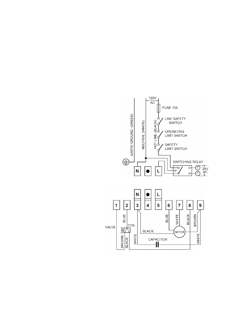
The burner may be controlied using either a DIRECT LINE VOLTAGE control circuit
(120V AC 60 cycle)
OR a LOW VOLTAGE control (24V AC 60 cycle) using a R8038A
Honeywell switching relay or equivalent.
Using the appropriate diagram below, make electrical connections to burner. All wiring
must be done in accordance with existing electrical codes, both national and local.
When all electrical connections have been made, the control box may be put back in
place on the sub-base.
WARNING: DO NOT activate burner until proper oil line connections have been
made, or failure of the pump shaft seal may occur.
APPLICATION FIELD WIRING
DIRECT LINE VOLTAGE
120 V
LOW VOLTAGE
AC
FUSE 15A
^6
/
LINE
SAFETY
g
/
SWITCH
^■6 / OPERATING
/ LIMIT SWITCH
b o / SAFETY
^
J
LIMIT SWITCH
N
FACTORY
WIRED
SUB-BASE
D5995
REMOTE SENSING OF SAFETY LOCKOUT: The SAFETY SWITCH in the 530SE
CONTROL BOX is equipped with a contact allowing remote sensing of burner lockout.
The electrical connection is made at terminal 4 (•) on the SUB-BASE. Should lockout
occur the 530SE CONTROL BOX will supply a power source of 120Vac to the con
nection terminal. The maximum allowable current draw on this terminal (4) is 1 Amp.
WARNING: If a neutral or ground lead is attached to this terminal, the CONTROL
BOX on the burner will be damaged should lockout occur.
F 1 0 - 6