Sears 944.36201 User Manual
Page 7
Attention! The text in this document has been recognized automatically. To view the original document, you can use the "Original mode".
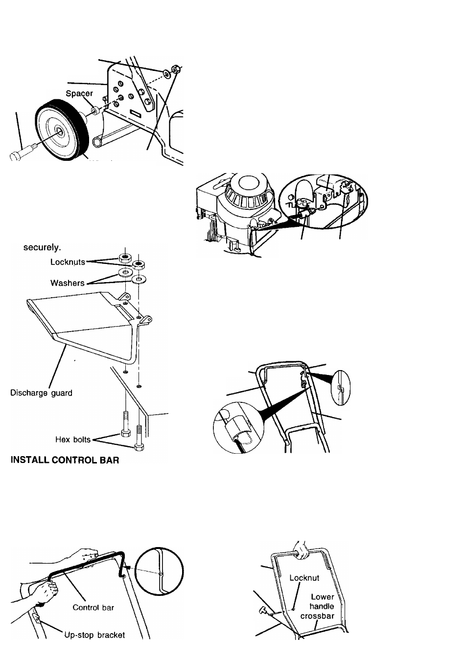
1-1/4" diameter Washer
(rear wheel only)
Mower housing
Shoulder
bolt
3/8-16
Wheel Locknut
ASSEMBLE DISCHARGE GUARD
1
.
2.
3.
Place discharge guard on top of lawn
mower discharge opening.
Install two (2) 1/4-20 x 3/4 hex bolts
through housing and discharge guard.
Install two (2) 3/4" diameter washers
and two (2) 1/4-20 locknuts. Tighten
1
.
2
.
Position control bar so flattened
section with hole is on opposite side
of handle as up-stop bracket.
Insert one end of control bar into
handle hole on inside of handle.
Carefully push in on opposite end of
control bar and insert into hole on
opposite side of handle.
ASSEMBLE ENGINE ZONE CONTROL
CABLE TO ENGINE
Cable attaches under brake arm cover,
(opposite side of engine as spark plug).
1
.
2
.
3.
Straighten cable and find the end with
the small plastic fitting.
Hook “Z" bend fitting on inner wire of
cable into hole in brake arm of engine.
Align tapered end of small plastic
fitting with hole in mounting bracket
and push until fitting snaps into place.
Mounting bracket
Brake
arm
Small plastic
fitting
ASSEMBLE ENGINE ZONE CONTROL
CABLE TO UPPER HANDLE
Attach cable opposite upstop bracket.
1. Route cable below crossbar of lower
handle and up to control bar.
Hook “Z” bend fitting on inner wire into
hole in control bar.
Attach cable fitting to upper handle.
Secure cable to lower handle with
wire tie.
Upper handle-
2
.
3.
4.
Control bar
Up-stop
bracket
Engine
zone
control
cable
INSTALL STARTER ROPE
1. Put threaded end of rope guide
through hole in side of upper handle
above lower handle crossbar. Secure
with 1/4-20 locknut.
Hold control bar against upper handle
and slowly pull engine starter rope out
until it will slip into loop of rope guide.
2
.
Upper handle
Rope guide
Engine
starter rope