Downflow furnace filter table, Combustion area and vent system, A caution – Carrier 58VCA User Manual
Page 9: A danger, Heading south for the winter
Attention! The text in this document has been recognized automatically. To view the original document, you can use the "Original mode".
DOWNFLOW FURNACE FILTER TABLE
DOWNFLOW
FURNACE
FILTER SIZE*
FILTER
CASING WIDTH
(IN.)
TYPE
All
(2)
16
X 20 X
1
Cleanable
4. Lower filter down along side of the blower and remove from
the furnace.
To remove the second filter, lift from V-shaped channel
and remove same way as left side filter.
Inspect the filters. If torn, replace the filter.
Wash the filters (if dirty) in a sink, bathtub, or outside
with a garden hose. Always use cold tap water. A mild liq
uid detergent may be used if necessary. Spray water
through the filter in the opposite direction of airflow
through the cross-mesh binding side. Allow filter to dry.
Reinstall clean filters with the cross-mesh binding side
facing the furnace blower.
Replace blower door and turn ON electrical supply to your
furnace. (See Pig. 30.)
8
.
9.
S" i «
’ 1
• i •
“
L i t
lï^ i
. ! .
i
1 \
5 i n
? 1
-iiBL
A88591
A87387
COMBUSTION AREA AND VENT SYSTEM
Visually inspect the combustion area and vent system before
each heating season. Make sure that all PVC pipes leading into
the combustion area and vent are free from any cracks and sags.
Also check the combustion-air intake and vent pipes on the
outside of your home for blockage.
When dirt, soot or rust is allowed to build up, your furnace can
suffer a loss of efficiency and perform improperly. Accumula
tions on the main burners can result in their firing out of nor
mal sequence. This delayed ignition will create an alarmingly
loud sound.
A CAUTION
If your furnace makes an especially loud noise when the
main burners light, shut down your furnace and call your
dealer.
To inspect the combustion area and vent system, you will need
a flashlight. Refer to Fig. 3 or 4, and proceed as follows:
1. Tbrn OFF the electrical supply to your furnace and remove
the access doors. (See Fig. 10 and 11, or 12.)
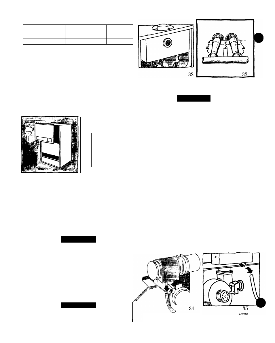
2. Remove burner enclosure front. (See Fig. 31 or 32.)
Inspect the gas burners and pilot area for dirt, rust, or scale.
(See Fig. 33.) Then inspect the vent outlet area and vent pipe.
A CAUTION
If dirt, rust, soot, or scale accumulations are found, call
your dealer. Do not operate your furnace.
A86057
A91065
3. Inspect the vent pipe for sags, holes, cracks, or discon
nections.
A DANGER
If holes are found in the vent pipe, or if it has become dis
connected, toxic fumes can escape into your home. DO
NOT OPERATE YOUR FURNACE. Call your dealer for
service.
4. Reinstall the burner enclosure front.
5.
6
.
7.
If your furnace is free of the above conditions, replace the
blower access door and restore electrical power to your fur
nace. (See Fig. 14, or 15 and 16.)
Start your furnace and observe its operation. Watch the
burner flames to see if they are clear blue, almost transpar
ent. The pilot flame should be well defined. (See Fig. 33.) If
you observe a suspected malfunction, or the burner flames
are not clear blue, or the pilot flame not well defined, call
your dealer.
If your furnace is operating properly, reinstall the control
access door.
HEADING SOUTH FOR THE WINTER?
DON’T FORGET YOUR FURNACE!
Since the furnace uses a condensing heat exchanger, some wa
ter will accumulate in the unit as a result of the heat transfer
process. Therefore, once it has been operated, it cannot be
turned off and left off for an extended period of time when tem
peratures will reach 32°F or lower, unless winterized. Follow
these procedures to winterize your furnace:
1. Mix a solution of equal amounts of ethylene glycol (Pres
tone II antifreeze coolant or equivalent) and water.
2. Tbrn OFF electrical supply to furnace. (See Fig. 10.)
3. Remove control access panel. (See Fig. 11 or 12.)
A86058
4. Disconnect drain tube from bottom of inducer vent outlet.
(See Fig. 34 or 35.)