Upflow furnace filter table, Caution – Carrier 58VCA User Manual
Page 8
Attention! The text in this document has been recognized automatically. To view the original document, you can use the "Original mode".
CAUTION
Never operate your furnace without a filter in place. Doing
so may damage the furnace blower motor. An accumulation
of dust and lint on internal parts of your furnace can cause
a loss of efficiency.
The air filter is normally located in the blower compartment.
(See Fig. 3.) Filters for the downflow furnaces are normally lo
cated in the return-air plenum above the blower. If the filters
have been installed in another location, contact your dealer for
instructions. To inspect, clean and/or replace the air filter(s),
follow these steps;
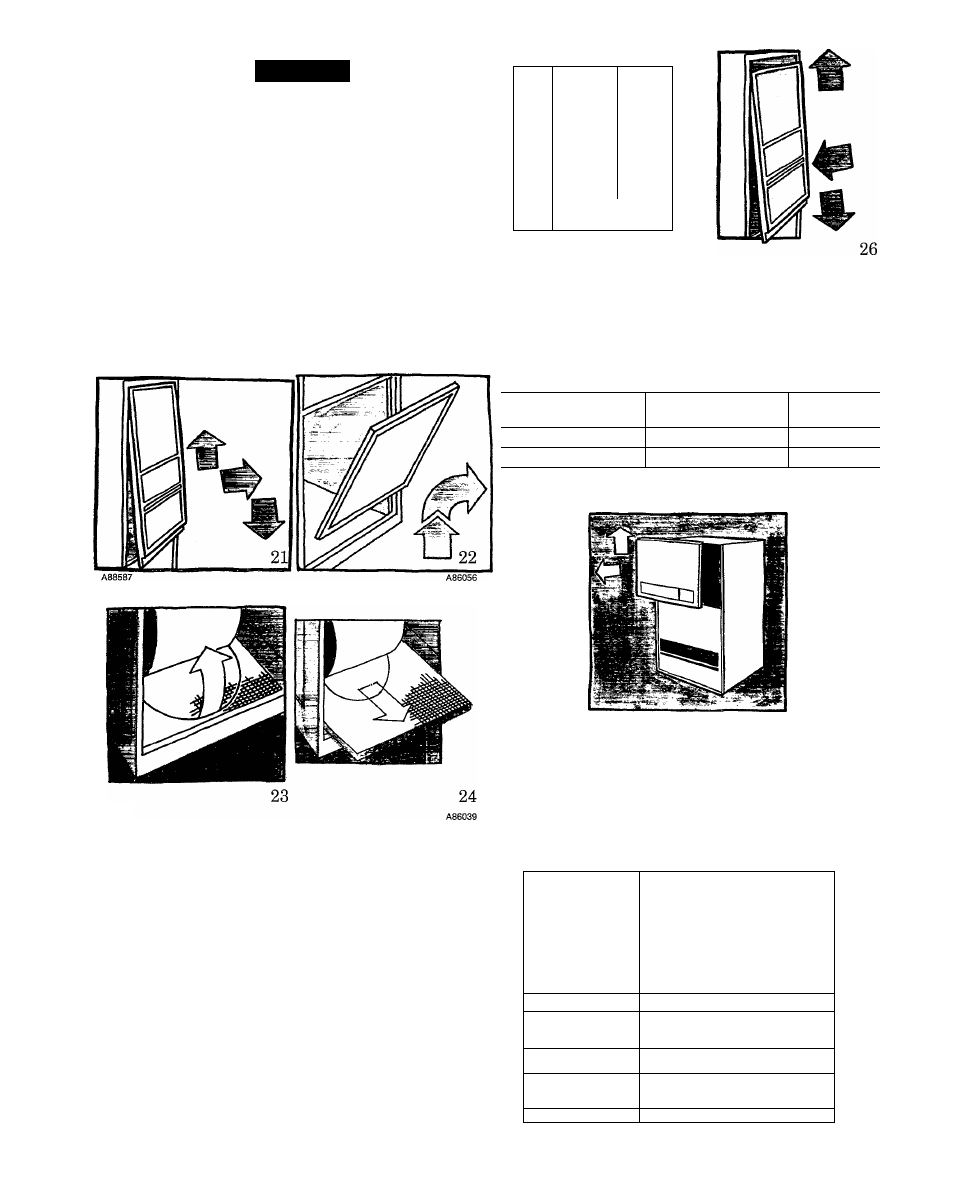
• UPFLOW FURNACES ONLY:
1. Tirn OFF the electrical supply to the furnace. (See
Fig. 19.)
2. Remove control and blower access doors. (See Fig. 21
and 22.)
№
1
*
y
25
A88588
A88589
If your furnace filter needs to be replaced, be sure to use the
same size and type of filter that was originally supplied. Use the
furnace filter table and compare your furnace size with the
proper filter size.
A86038
3.
4.
5.
Push filter retainer toward the back of the furnace until it
clears the flange on the furnace casing. (See Fig. 23.)
Gently remove the filter and carefully turn the dirty side
up (if dirty) to avoid “spilling” dirt from the filter. (See
Fig. 24.)
Inspect the filter. If torn, replace it.
6. Wash the filter (if dirty) in a sink, bathtub, or outside with
a garden hose. Always use cold tap water. A mild liquid de
tergent may be used if necessary. Spray water through the
filter in the opposite direction of airflow (through the
cross-mesh binding side). Allow filter to dry.
Reinstall the clean filter with the cross-mesh binding side
facing the furnace blower.
Push filter retainer toward back of the furnace until it will
go behind the flange on the furnace casing.
Replace blower and control access doors and turn ON elec
trical power to your furnace. (See Fig. 25 and 26.)
7.
8
.
9
.
UPFLOW FURNACE FILTER TABLE
UPFLOW FURNACE
FILTER SIZE*
FILTER
CASING WIDTH
(IN.)
TYPE
17-1/2
(1) 15-7/8 X 27-3/4 x 1
Cleanable
21
(1) 19-1/2 X 27-3/4 X 1
Cleanable
*Furnace with a side return-air inlet may have a different filter size.
Measure the filter to obtain the correct size.
27
A88590
• DOWNFLOW FURNACES ONLY: Tvo filters are located
in the return-air plenum above the blower (above line-of-
sight) attached to the top of the furnace. (See Fig. 28.)
1. Tbrn OFF electrical supply to the furnace. (See Fig. 19.)
2. Remove blower access door. (See Fig. 27.)
3. Remove the left side filter by tipping the filter toward the
center—raise it from the V-shaped channel in which it
rests. (See Fig. 28 and 29.)
m
S||||
< t o
1
o
□!
28
A92156 k
I
29
A92155