A warning, Step 5 — start-up, Refrigerant charging (refer to tables 4 and 5) – Carrier 38EH User Manual
Page 4: A caution, Warning, Caution
Attention! The text in this document has been recognized automatically. To view the original document, you can use the "Original mode".
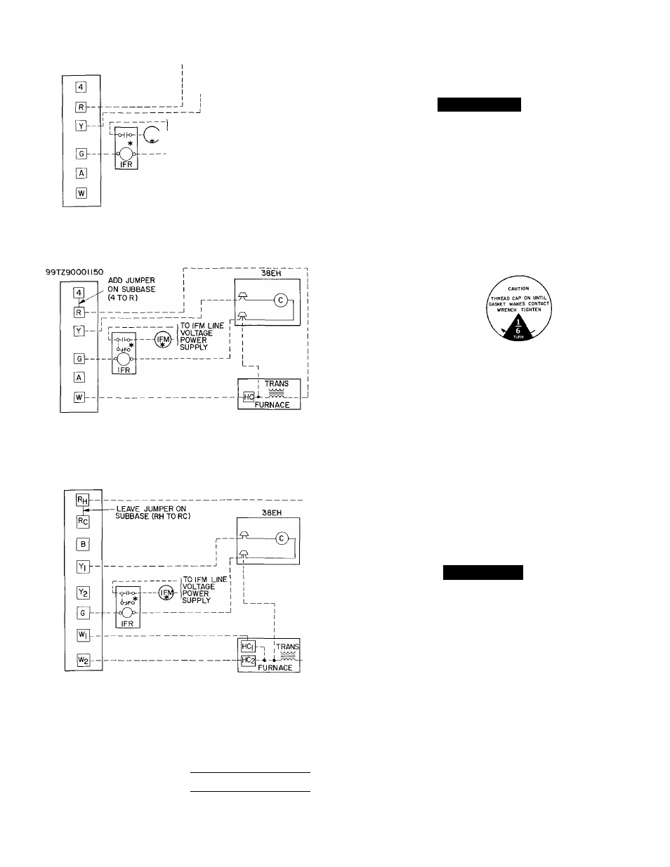
THERMOSTAT SUBBASE
99TZ90008I25 OR
99TZ9000II50
38EH
___ ^
TO IFM LINE
VOLTAGE
IFM)-|POWER
SUPPLY
TRANS
ARRANGEMENT A-(COOLING ONLY)
THERMOSTAT SUBBASE
ARRANGEMENT B-ONE TRANSFORMER
(COOLING AND ONE-STAGE HEATING)
THERMOSTAT SUBBASE
99TZ90036I20
ARRANGEMENT C-ONE TRANSFORMER
(COOLING AND TWO-STAGE HEATING)
*IFR and IFM are located in furnace on heating-cooling applica
tions If accessory IFR is required for cooling-only applications,
locate (IFR) in fan coil
c
— Contactor (12-va)
^ Field Splice
HC
— Heating Control
IFM
— Indoor Fan Motor
_ Field Wiring
IFR
— Indoor Fan Relay
Trans — Transformer
Factory Wiring
NOTE' Refer to unit wiring label for wire colors C to G and Cto Y
connections.
Fig. 5 — Control Circuit Connections
90 seconds, which provides additional cooling after
compressor has cycled off. Refer to separate installation
instructions packaged with fan time delay (shipped with
unit).
A
WARNING
To avoid personal injury, be sure indoor blower has
stopped before attempting service or maintenance.
Step 5 — Start-Up
1
.
2
.
3.
When equipped with a crankcase heater, energize
heater a minimum of 24 hours before starting unit. To
energize heater only, set thermostat at OFF position
and close electrical disconnect to outdoor unit.
Backseat (open) liquid and suction line service valves.
Unit is shipped with valve stem(s) frontseated, and
caps installed. Replace stem caps after system is opened
to refrigerant flow (backseated). Replace caps finger
tight and tighten additional 1/6 turn with wrench
See sticker on valve cap.
4. Set thermostat selector switch at OFF.
5. Set room thermostat at desired temperature. Be sure
set point is below indoor ambient temperature
6. Close electrical disconnects to energize system
7. Set room thermostat at COOL and fan switch at FAN
or AUTO, as desired. Operate unit for 15 minutes.
Check system refrigerant charge. See Refrigerant
Charging, below.
Motors and controls are designed to operate satis
factorily in the voltage range shown in Table 3. If neces
sary to use manifold gages for servicing, refer to Carrier
Standard Service Techniques Manual, Chapter 1, Refrig
erants, page 1-5, Fig. 8, for bypass method of returning
charge to system. Removal of liquid line charging hose
without following these precautions could result in some
loss of charge.
Refrigerant Charging (Refer to Tables 4 and 5)
A
CAUTION
To prevent personal injury, wear safety glasses and
gloves when handling refrigerant. Do not overcharge
system. This can cause compressor flooding.
1. Operate unit a minimum of 10 minutes before check
ing charge.
2. Measure suction pressure by attaching a gage to
suction valve service port.
3.
Measure suction line temperature by attaching a
service thermometer to unit suction line near suc
tion
valve.
Insulate
thermometer
for
accurate
readings.
4. Measure outdoor coil inlet air dry-bulb temperature
with a second thermometer.
5. Measure indoor coil inlet air wet-bulb temperature
with a sling psychrometer.
6. Refer to Table 4. Find air temperature entering out
door coil and wet-bulb temperature entering indoor
coil. At this intersection note the superheat.
7. Refer to Table 5. Find superheat temperature and
suction pressure, note suction line temperature.