Fig. 3 — repair of mechanical connection, Compatible fitting repair, Step 4 — make electrical connections — be – Carrier 38EH User Manual
Page 3: Fig. 4 — line power connections, Step 4 — make electrical connections, Table 3 electrical data (60 hz)
Attention! The text in this document has been recognized automatically. To view the original document, you can use the "Original mode".
CUT HERE
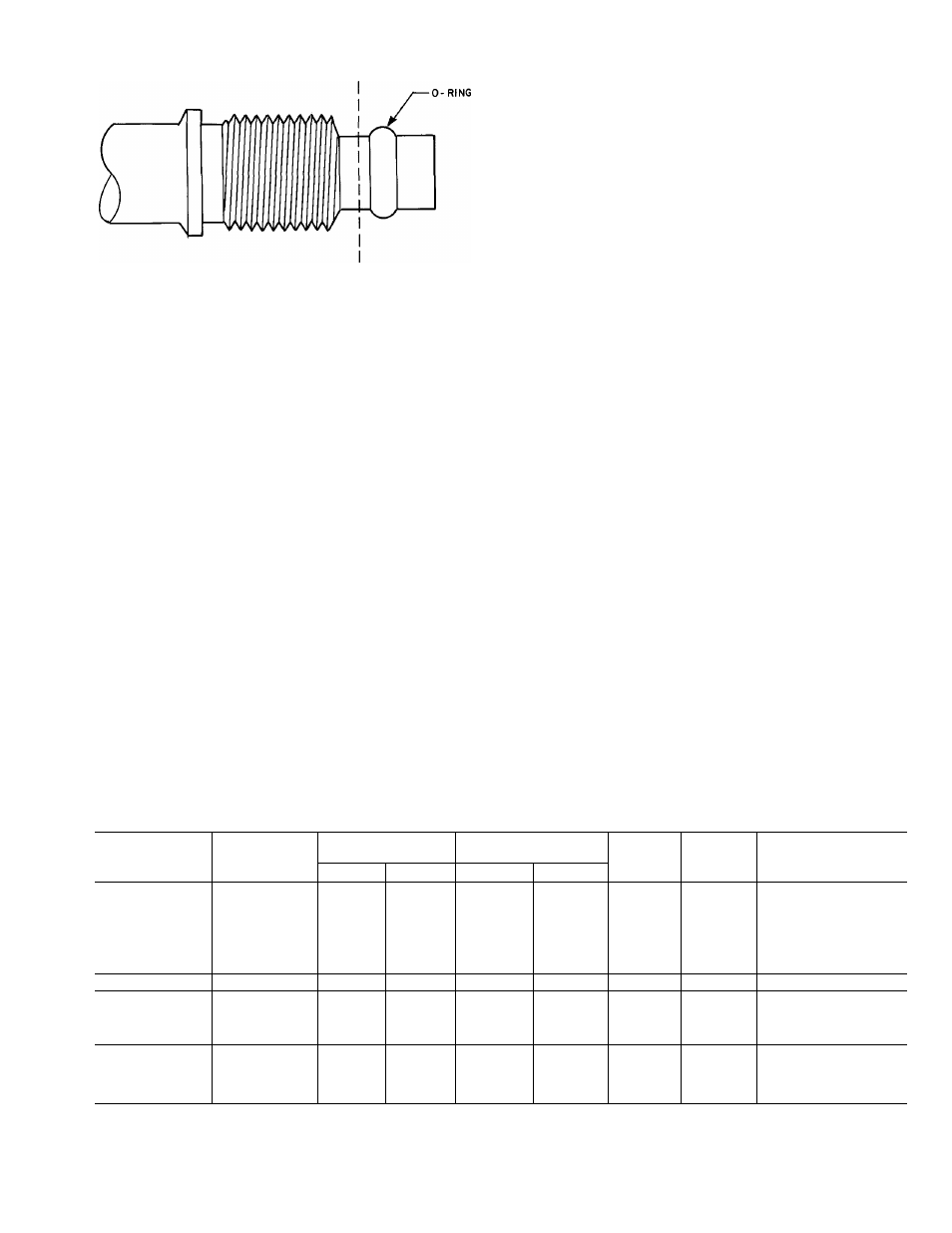
Fig. 3 — Repair of Mechanical Connection
Compatible Fitting Repair
MECHANICAL
CONNECTION
—
Frontseat
unit
service valves. Relieve refrigerant pressure from tubing.
Back off locknut from Compatible Fitting onto tube.
Cut fitting between threads and 0-ring. See Fig. 3.
Remove tubing section remaining in threaded portion
of fitting. Discard locknut.
Clean, flux and insert new tube end into remaining
portion of Compatible Fitting. Wrap valve in wet rag to
prevent damaging factory-made joints. Heat and apply
low-temperature (430 F) solder.
SWEAT
CONNECTION
—
Frontseat
unit
service
valves. Relieve refrigerant pressure from tubing. Clean
and flux area around leak. Repair, using low-temperature
(430 F) solder
Evacuate or purge evaporator coil and tubing system.
Add refrigerant charge. See Refrigerant Charging.
Step 4 — Make Electrical Connections
— Be
sure field wiring complies with local and national fire,
safety and electrical codes, and voltage to system is
within limits shown in Table 3. Contact local power
company for correction of improper line voltage.
NOTE; Operation of unit on improper line voltage
constitutes abuse and could affect Carrier warranty. See
Table 3. Do not install unit in system where voltage may
fluctuate above or below permissible limits.
See Table 3 for recommended fuse sizes. When making
electric connections, provide clearance at unit for refrig
erant piping connections.
INSTALL BRANCH CIRCUIT DISCONNECT PER
NEC of adequate size to handle unit starting current.
Locate disconnect within sight from and readily acces
sible from unit, per Section 440-14 of NEC (National
Electrical Code^
ROUTE LINE POWER LEADS — Extend leads from
disconnect through power wiring hole provided (see
Fig. 1) and into unit splice area. Remove control box
cover to gain access to unit wiring.
CONNECT GROUND LEAD AND POWER WIRING
— Connect ground lead to ground connection in control
box for safety. Then connect power wiring. See Fig. 4.
Splice line power leads to yellow and black pigtails. Use
wire nuts and tape at each connection. Connect unit
wiring to copper power wiring only.
I-PHASE
CONN. TO
DISCONNECT
PER NEC
-------- GROUND LEAD -
____________________ .4=^
Q SPLICE CONNECTIONS
--------------FIELD WIRING
------------- FACTORY WIRING
-^GROUNDING LUG
-
— BLK------------------
YEL--------
I- PHASE
COND UNIT
Fig. 4 — Line Power Connections
CONNECT CONTROL POWER WIRING — Route
24-v control wires through control wiring hole and
connect to pigtails supplied with unit (Fig. 1). Splice
control leads to brown and blue pigtails on all units.
See Fig. 5.
Use furnace or fan coil transformer as 24-v (40-va
minimum) supply for system as shown in Fig. 5, or use
accessory transformer.
NOTE: Some 38EH units are equipped with a fan time
delay. This permits indoor fan to continue to operate for
Table 3 Electrical Data (60 Hz)
OUTDOOR
V/PH
OPER VOLTS*
COMPR
FAN
FLA
MCA
MAX FUSEt OR
HACR TYPE
UNIT 38EH
Max
Min
LRA
RLA
CKT BKR (Amps)
015
37 5
64
07
87
15
018
43 0
78
0.7
105
15
024
66 0
140
07
18 2
30
030
208-230/1
253
197
88 0
18 6
09
24 2
40
036
88 0
18 1
0.9
23 6
40
042
108 0
21 4
0.9
27.7
45
048
110.0
26 0
25
35.0
50
060
230/1
253
207
130 0
29 3
1 9
38.5
60
036-5
65.1
97
09
15.3
25
042-5
208-230/3
253
187
74.0
17.1
09
22.3
35
048-5
92 0
19 6
2 5
27 0
45
060-5
98 0
20 9
1.9
28.0
45
036-6
32 8
4 76
1 6
74
15
042-6
048-6
460/3
508
414
37 0
46 0
69
72
1 6
1 6
103
106
15
15
060-6
49.0
104
1 6
145
20
FLA — Full Load Amps
HACR — Heating, Air Conditioning, Refrigeration
LRA — Locked Rotor Amps
MCA — Minimum Circuit Amps
RLA — Rated Load Amps
‘Permissibie iimits of the voltage range at which unit wiii operate
satisfactoriiy
fTime-delay fuse
NOTE; Controi circuit is 24 v on ali units and requires externai
power source
886