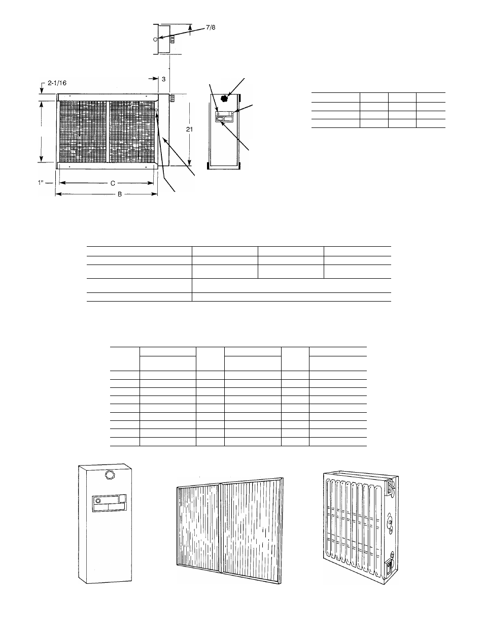
Table 3—pressure drop at various airflows, Table 1—dimensions (in inches), Fig. 3^view of major components – Carrier 31KAX User Manual
Page 2
Attention! The text in this document has been recognized automatically. To view the original document, you can use the "Original mode".
.REAR MOUNTING FLANGE
A---------------------------►
ELECTRICAL ENTRANCE
S-1/2 FOR DUCT APPLICATION
Jr
OPERATION
,KNOB
LIGHT
16-7/8
Table 1—Dimensions (In Inches)
ON/OFF SWITCH
LOGO
Model
A
B
C
31KAX012
24-3/4
21-3/4
19-1/2
31KAX016
27-1/4
24-1/4
22
31KAX020
31-1/2
28-1/2
26-1/4
REMOVABLE
POWER DOOR
ELECTRICAL ENTRANCE (5/8" DIA.)
FOR FURNACE APPLICATIONS)
Fig. 2—Dimensional Drawing
Table 2—Component Information
A91466
Model
31KAX012
31KAX016
31KAX020
Air Volume Range
300-1400
500-1800
700-2000
Electrical Data (input
to power door)
120 volts,
single phase, 60 Hz
120 volts,
single phase, 60 Hz
120 volts,
single phase, 60 Hz
Eiectrical Data (output
to collector cell)
120 volts—1.0 milliamps @ 7300 VDC
Approx Ship. Wt. 120V
50
54
57
Table 3—Pressure Drop At Various Airflows
31KAX012
31KAX016
31KAX020
CFM
Pressure Drop
Inches wc
CFM
Pressure Drop
Inches wc
CFM
Pressure Drop
Inches wc
300
0.005
500
0.010
700
0.010
400
0.010
600
0.025
800
0.013
600
0.020
800
0.020
1000
0.018
800
0.030
1000
0.028
1200
0.023
1000
0.050
1200
0.035
1400
0.030
1100
0.060
1400
0.045
1600
0.038
1200
0.065
1600
0.065
1800
0.045
1300
0.075
1700
0.070
1900
0.048
1400
0.085
1800
0.080
2000
0.050
NOTE: Using the electronic air cleaner on air
for 012-size unit, 500 cfm for 016-size units,
duct systems designed for airflows lower than 300 cfm
or 700 cfm for 020-size units, is not recommended.
A91467
Fig. 3^View of Major Components