Step 3, Connection to external connection box, Step 4 – Carrier ASPB07-1SI User Manual
Page 7: Mounting the automatic transfer switch, Steps, Connection of emergency circuits, Misi, Continued on page 8
Attention! The text in this document has been recognized automatically. To view the original document, you can use the "Original mode".
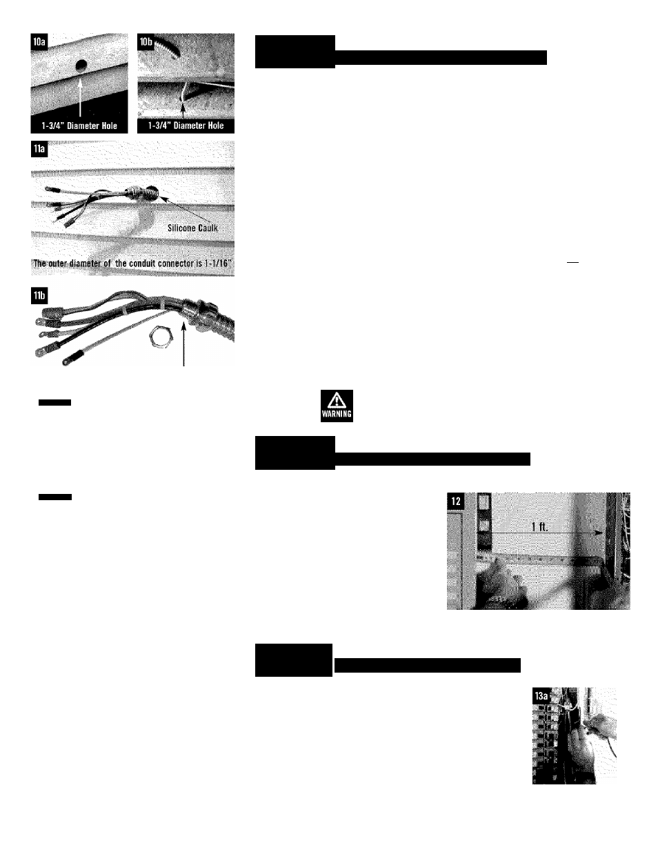
The outer diameter of the threaded end is 15/16".
A
DANGER
Although you may choose to perforrh
electrical connections yourse^^^
CARRIER recommends that a
licensed electrician or individual with complete
knowledge of electricity perform the procedures
in sections 12.13a. and 13b.
A
DANGER
Switch service main circuit breaker
to off" or open posifion prior to
removal of cover or removal of any
wiring of fhe main electrical distribution panel.
The wires connected to
the service main circuit
breaker
remain
live
or
‘ hot". Avoid contact with
these
wires
and
the
service main circuit breaker connection lugs.
I I I I I I
STEP 3
CONNECTION TO EXTERNAL CONNECTION BOX
10a. Determine where the flexible conduit will pass through the house from inside to outside.
When you are certain you have clearance on each side and within the wall, drill a small pilot
hole through the wall to mark the location.
10b. Using a hole saw, drill a 1-3/4 inch diameter hole in the house’s wall to allow the conduit
to fit through.
11a. From the inside of the house, feed the end of the 30-foot conduit (which is pre-wired from
transfer switch) through the wall to outside.
lib. Remove the threaded lock nut from the conduit coupling.
—
-
M
MiSi
11c. Lift cover. Remove internal oover plate screw and internal cover.
Remove the knock out in the lower right corner of the external
connection box. From the rear of the connection box, feed wires
& 4 pin plug into box. Slip the lock nut over wires and plug and
tighten securely onto conduit coupling. Using appropriate
Ground
fasteners, mount external connection box over pre-drilled hole to
Screw
fully conceal the hole. Seal around the hole and conduit with
silicone caulk from both the inside and outside of the home.
Knockout
Also, caulk around the sides and top of the box to seal the edges to the siding or wall.
Connect wires to lugs; Black to black, white to white, and red to red. Torque nuts to 20
in/lbs. Snap together the 4-pin plug connector. Loosen nut from grounding lug and attach
ground wire (green) from conduit. Reinstall nut and tighten to 45 in/lbs. Reinstall internal
cover plate and screw. Close cover and install lock. This wiring is complete.
The external connection box must be locked to
ensure safety and to discourage tampering.
STEP 4
MOUNTING THE AUTOMATIC TRANSFER SWITCH
12.
Locate
automatic
transfer
switch
with
built-in
emergency
load
main
distribution
panel.
The
automatic
transfer switch with built-in load center can
be located to the left or right of main
distribution
panel.
Hold
transfer
switch
against
the
mounting
surface.
Level
the
transfer
switch
and
mark
the
mounting
holes. Drill the appropriate size pilot holes.
Mount
automatic
transfer
switch
with
built-
in
load
center
to
mounting
surface
with
appropriate fasteners.
center within one foot of
NOTE: Balance must be maintained when moving
circuit
locations
from
main
electrical
distribution panel to emergency load center.
Circuit breaker positions alternate buss bars
vertically. Circuits sharing a neutral wire should
either be moved together to adjacent positions in
emergency load center or not moved. If you are
unsure of proper procedure or if your installation
differs from that described in this guide, consult
a licensed professional at this time.
STEPS
CONNECTION OF EMERGENCY CIRCUITS
13a.
Remove
the
main
electrical
distribution
panel
cover.
Remove
appropriate size knockout from the bottom or side of the main panel.
(A 2-foot flexible conduit is pre-wired from the transfer switch with
built-in
load
center.)
Remove
threaded
lock
nut
from
conduit
coupling. Feed all wires through knockout into main panel. Slip lock
nut over wires and tighten securely on conduit coupling. Remove the
black (hot) wire from a circuit breaker that protects a circuit you
want to have powered in the event of a power failure. -
continued on
page 8