Step 1, Site preparation, Step 2 – Carrier ASPB07-1SI User Manual
Page 6: Fuel hook up & check for leaks, Mm wsm, Fahrrctt^w'xtl, Will bis\ will be \(fi^lliitg, Cutting, Reconfiguringthefuelsystem”\n
Attention! The text in this document has been recognized automatically. To view the original document, you can use the "Original mode".
STEP 1
*
mm
wsm
B
SITE PREPARATION
1.
It will be necessary to pay a visit to your local municipal offices
to apply for a building permit. Building permits are necessary to
ensure
proper
installation,
safety
and
adherence
to
all
local
building
code
specifications.
The
location
and
phone
number
can be found in the government section of your local phone book.
2.
Plan the location of your generator.
NOTE: Do not place the
generator directly under a window.
Select an area outside of
your home nearest your incoming gas service.
3.
Arrange
for
installation
of
rigid
gas
piping
(per
local
code
specifications) to the location where you intend to position your
generator. Fuel piping should include a fuel shut-off valve. The
termination
of
the
rigid
piping
should
be
aligned
with
the
generator fuel inlet located at the rear of the compartment.
4.
Clear an area 5-1/2 feet by 5 feet minimum of grass and vegetation
to a depth of 5 inches. This includes the distance the generator
should be set away from any structure (3 feet) and 6 inches beyond
the width and length of the generator mounting pad (48” Lx24” W).
NOTE: Local codes may supercede these requirements.
5.
Lay black poly-film to cover the area.
6.
Fill the area to ground level with pea gravel or crushed stone.
7.
Place the generator, which is attached to the mounting pad, on
the area you have just prepared.
‘ 8a. Drive an 8 ft. grounding rod into the ground to grade.
8b
STEP 2
Attach one end of the grounding strap (No. 12 AWG stranded
copper wire) to grounding rod and the other end to the grounding
lug (located at rear corner of unit). Make sure grounding rod and
strap are not exposed above ground level. (NEC code applies to
grounding method.)
NOTE: Generator mode switch should be placed in the “off”
position. Generator main line circuit breaker should be
switched to “off” or open position.
FUEL HOOK UP & CHECK FOR LEAKS
ITEMS YOU MUST PURCHASE:
B:attery
.-VAutani0tive.type/G:raup;26;
negaTive
Itojind. ntinimtiffl ;35t)i.CA .at T)'. F'/?: kW) .oral
ifiinimijnv.52S.tGA. at0'"Fi;T0iM; 13-kìi/ ani
40 Anjp (.7;kW);;ari7(3jAhlp :flDjkW^
T.5 TrW) jdouhjevpplejcirciJif: ;l)reaker;(iyiusT bf
Gornpat ifjfe I vvjfh'yoti ryma in. di stri butiovl pa nel;;);:
GfO:Uociing rod)with groundJh.g istrap : : j :: : : : :
•; PàdiockTTo.lock exfefnal:.cpnhec;tidndpx); 1 ;:
Crus-hpct Istòriero.r ;pea; gravel Tapproxfmately
1.0-1.2 cLi.hic feet)'-. :/■■ ■■. '
Black. p.cily-t.ii:m ór othe:r wegetatipn. blDcking
fahrrctt^W'xtL' ^............... ' "
Silicone Caulk i
Pipe.: sea la nt . ' (suita bTe. 1 forv ga.sepus Tuet >
connections}. -
:C-'.V.;V'.r
.■ .■ j
Fasteners: (to hiount externaToonnection ^brscs
a.n.d;.-automatic ■ tvansterIswitcb with: builtr«1,:
emergency IqadlcehteflVjl '.■■t-'t-' .-'j' .■'.■ jt j j j j
TOOLS REQUIRED:
Dr i lb driiTti
will bis\
Will be \(fi^lliitg
ti/?f7
cutting},
open-endj wrenches.: orlfidjusta.b.le.
wrenches.: Isocketi wreh.ches. or: :niut Vdriivers.:
standard and;Phil.lfps screwdrivers., level,: sledge:
hammer,
xhannel-tock:
plierstspavie.
/shovel.:
pehciT.a:nd.;sa:fe:ty goggles,/////////■■
PLEASE NOTE:
Natural gas pressure to the fuel
inlet on the generator must be 5 - 7” W.C. (0.18 to
0.25 psi). LP gas pressure to the fuel inlet on the
generator must be 10 -12" W.C. (0.36 to 0.43 psi)
A primary regulator must be used if unit is
connected to an LPfuel tank (Primary regulator is
not supplied).
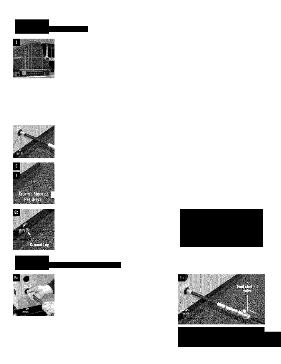
9a.
Make
the
connection
between
the
rigid
fuel
piping
and
the
generator using the supplied threaded flexible fuel line. The flex
hose should be straight.
Do not bend the hose in place of using
pipe elbows.
Use a pipe sealant suitable for gaseous fuel
connections.
Check
connections
for
leaks
by
opening
manual
fuel shut-off valve and swab or spray connections with soapy
water. If a leak exists the area will bubble with the presence of
the soapy water.
9b. It a leak is located, shut off fuel, and disconnect flexible piping.
Dry the threaded ends and reapply an adequate amount of pipe
sealant.
Reconnect
flexible
fuel
line,
open
fuel
supply
and
recheck for leaks. If leak still exists, repeat step 9b.
Qonverting to LP gas
From the factory, units are set-up for natural gas
operation. To convert for operation on LP gas refer to
“Reconfiguringthefuelsystem”\n
the
Owner’s Manual.