Installing the automatic transfer switch (a.t.s.) – Winco ATS User Manual
Page 6
PAGE 4
60706-131
8107-00
INSTALLING THE AUTOMATIC
TRANSFER SWITCH (A.T.S.)
GENERAL INFORMATION
*************
***** WARNING *****
*************
EQUIPMENT DAMAGE- Protect the switch from con-
struction grit and metal chips to prevent a malfunction or
shortened life of the switch.
The Automatic Transfer Switch connects the load (lights,
furnace, outlets, etc.) to the normal power line during
standby. When normal power fails, the A.T.S. starts the
engine generator set, disconnects the power line and
then connects the load to the standby generator set.
When normal power is restored, the automatic switch
retransfers the electrical load to the normal service and
stops the engine. The A.T.S. panel should be mounted
as close to the distribution panel as possible.
*************
***** WARNING *****
*************
All wiring must be done by a licensed electrician, and
must conform to the national electrical code and comply
with all state and local codes and regulations. Check
with your electrical inspectors before proceeding!
Before installing the Automatic Transfer Switch you must
first ensure that the line side contractor will be of
sufficient size to handle your complete service. (i.e. the
main line breaker must not be larger than the line side
contactor rating.) If you will not be able to transfer the
complete electrical system it will be necessary to install
a secondary emergency distribution panel.
*************
***** DANGER *****
*************
Be certain the operation selector switch on the front of the
A.T.S. Control is in the “stop” position and the main power
switch “off”. For your own protection, verify these impor-
tant safety precautions yourself with reliable instruments
before proceeding.
A.C. ELECTRICAL CONNECTIONS
*************
***** WARNING *****
*************
A FUSED DISCONNECT/CIRCUIT BREAKER MUST BE
INSTALLED BETWEEN THE GENERATOR AND THE
A.T.S. PANEL TO PREVENT OVERLOADING AND
BURNING OUT OF THE GENERATOR. FAILURE TO
PROVIDE A FUSED DISCONNECT OR CIRCUIT
BREAKER, FOR GENERATOR RATING WILL VOID
YOUR WARRANTY IN CASE OF GENERATOR FAIL-
URE.
SINGLE PHASE A.T.S. CONNECTIONS
The generator terminals (power in from the generator) in
the A.T.S are marked “GENERATOR - G1, G-N, G3”. The
“hot” leads G1 and G3 are wired to the generator side
contactor, terminals G1 and G3.
The line terminals (normal power source) in the A.T.S.
are marked “LINE - L1, L-N, L3”. The “hot” leads L1 and
L3 are wired to the line side contactor, terminals L1 and
L3.
The load terminals (power out to loads) in the A.T.S. are
marked “LOAD - T1, T-N, T3”. The “hot” leads T1 and T3
are wired to the load lugs T1 and T3.
All three neutral connections are made to the appropriate
neutral lugs. These lugs have been prewired common
in the A.T.S. A neutral to ground bond has also been
installed in the A.T.S. panel. If your system requires an
isolated neutral this bond, a copper jumper strap, should
be removed. If this jumper strap is removed remember
to properly ground the Automatic Transfer Switch using
the grounding lug provided.
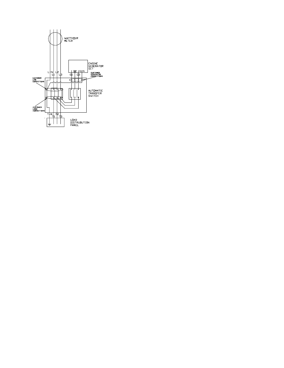
THREE PHASE A.T.S. CONNECTIONS
The standby generator terminals in the A.T.S are marked
“GENERATOR - G1, G2, G3 and G-N”. The “hot” leads G1,
G2 and G3 are wired to the generator side contactor,
terminals G1, G2 and G3.
The line terminals in the A.T.S. are marked “LINE - L1, L2,
L3” and L-N. The “hot” leads L1, L2 and L3 are wired to
the line side contactor, terminals L1, L2 and L3.
The load terminals in the A.T.S. are marked “LOAD - T1,
T2, T3 and T-N”. The “hot” leads T1 and T3 are wired to
the load lugs T1, T2 and T3.
FIGURE 5