Winco ATS User Manual
Page 5
PAGE 3
60706-131
8107-00
AUTOMATIC TRANSFER SWITCH SIZES
CONTACTOR SIZE
MODEL
VOLTAGE
PH LINE
GEN.
ATS-3/B 100/50
120/240
1
100 AMP 50 AMP
110/60ATS-3/B
120/240
1
110 AMP 60 AMP
ATS-3/A 100/100
120/240
1
100 AMP 100 AMP
ATS-4/A 100/100
120/208
3
100 AMP 100 AMP
ATS-17/A 100/100 120/240
3
100 AMP 100 AMP
ATS-18/A 100/100 277/480
3
100 AMP 100 AMP
ATS-3/A 225/100
120/240
1
225 AMP 100 AMP
ATS-4/A 225/100
120/208
3
225AMP
100 AMP
ATS-17/A 225/100 120/240
3
225 AMP 100 AMP
230/150ATS-3/B
120/240
1
230 AMP 150 AMP
230/150ATS-4/B
120/208
3
230 AMP 150 AMP
230/150ATS-17/B
120/240
3
230 AMP 150 AMP
ATS-3/A 225/225
120/240
1
225 AMP 225 AMP
ATS-4/A 225/225
120/208
3
225 AMP 225 AMP
ATS-17/A 225/225 120/240
3
225 AMP 225 AMP
ATS-18/A 225/225 277/480
3
225 AMP 225 AMP
ATS-3A 400/300
120/240
1
400 AMP 300 AMP
ATS-4A 400/300
120/208
3
400 AMP 300 AMP
ATS-17A 400/300
120/240
3
400 AMP 300 AMP
400/320ATS-3/B
120/240
1
400 AMP 320 AMP
Optional A.T.S. sizes are available to meet specific
needs. If you need a switch of a different size contact
WINCO, Inc.
INSTALLATION NOTES
The load current carrying wires (L) and (T) must be sized
to handle the maximum load current without excessive
voltage drop. By code, the wire must be heavy enough to
handle the full current rating of the main line circuit-
breaker (or fuse) in the entrance (or sub-panel) protect-
ing the transfer switch.
All wires should be installed in rigid or flexible conduit.
(Knockouts are provided in the control box)
Because of the many different types of service, feeder,
and distribution equipment, no specific wiring instruc-
tions can be provided. It is, however, recommended that
only copper wire be used. In all cases it is essential that
while the load is connected to the generator, there can be
absolutely no feedback from the generator to the power
line or the power line to the generator. When properly
installed, the normal A.T.S. control and safety systems
will eliminate all paths for feedback. Check with your
local electrical inspector on applicable local, state and
federal codes.
NOTE:
It is an excellent idea to install a disconnect in the
incoming power line wiring directly in front of the A.T.S.
panel. This will allow you to test the generator under
load. Should you ever have to work on the switch, you
will be able to disconnect the power and work on the
switch cold, without having the power company pull your
meter.
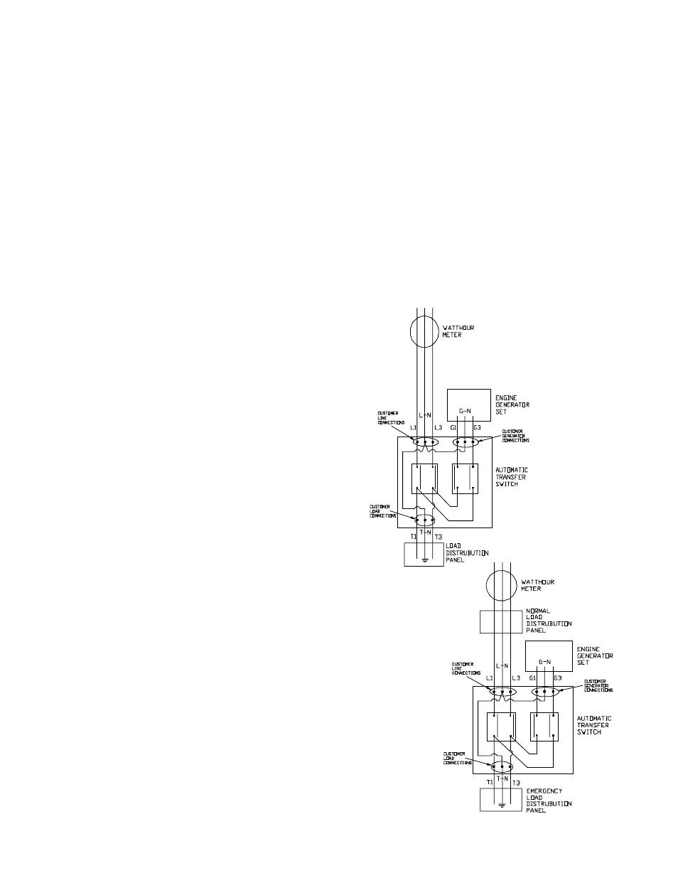
To wire the automatic transfer switch into the existing
wiring, first determine which circuits will be on the
emergency load circuit. If the entire load is to be
transferred, the transfer switch can be wired in directly
after the watt-hour meter or main entrance, provided the
service entrance ampere rating is within the transfer
switch’s rated capability. (See figure 3 and figure 5)
If only specific circuits are to be powered during power
failure conditions, an additional distribution panel
designated “emergency distribution panel” must be
installed. All selected emergency circuits are removed
from main distribution panels and reinstalled in the
emergency distribution panel. Suggested circuits:
freezer, refrigerator, furnace, emergency lights, sump
pump, emergency outlet circuits, etc. Total running load
must not exceed generator rating. (See figure 4)
FIGURE 3
FIGURE 4