Winco ASCO 300 Accessory 11BG User Manual
Module installation, Connecting the module
381339–252 B
ASCO POWER TECHNOLOGIES L.P.
50 Hanover Road, Florham Park, New Jersey 07932 USA
www.asco.com
page 1
Automatic Transfer Switches
for
Series 300
Accessory 11BG
Installation
Accessory 11BG module includes a programmable engine–
generator exerciser and power source availability contacts. It
can be added to a Series 300 Automatic Transfer Switch (ATS)
that has a Group 1 Controller. If an existing engine exerciser
(Acc. 11CD) is already installed, it must be disconnected first.
The Accessory 11BG module mounts directly behind the
Series 300 ATS operator interface on the inside of the
enclosure door. The module connects to the Series 300 ATS
operator interface board and Group 1 controller.
Kits K629830 & K749999 include the Acc. 11BG module,
mounting hardware, and all necessary wiring.
Tools
1/4”, 5/16” nutdrivers, small blade screwdriver
required:
your Series 300 ATS Operator’s Manual
for setting the DIP switches
ELECTROCUTION – FLASH HAZARD
Do not work on the transfer switch until
both the utility and generator are off.
Turn OFF both circuit breakers.
Module Installation
– Figures 2 & 3
1. With all power OFF, open the enclosure door. Locate
the operator interface (membrane controls) mounted
on the inside of the enclosure door. Use a 5/16”
nutdriver to remove (counterclockwise) the four hex
nuts from the corners of the operator interface. Do not
remove the operator interface board (Figures 2 & 3).
2. Install (clockwise) four standoffs (from the kit) onto
the four studs and tighten them with a 1/4” nutdriver.
3. Install the Acc. 11BG module on top of the operator
interface so that four standoffs fit through the corner
holes. Then install (clockwise) four 6–32 hex nuts (from
the kit) to secure the assembly. Tighten the nuts.
Connecting the Module
– Figures 1, 2, 4
1. With all power OFF, locate the two ribbon cables and
note direction and orientation of each cable.
2. Unplug the ribbon cable (coming from the Controller)
from the operator interface (J3 lower right side) and
reconnect it (same orientation) to the Acc. 11BG module
(J1 lower right side). See Figures 1, 2, & 4.
3. Connect the new ribbon cable (coming from the Acc.
11BG module upper right side) to the operator interface
(J3 lower right side) with the same orientation as the
original cable that was moved. See Figures 2 & 4.
4. Strip the insulation from both ends of the #16 gauge
white wire (from the kit). Connect this prepared wire
between Acc. 11BG module terminal 9 (right side) and
the Group 1 Controller terminal 4 (bottom left). Figure 4.
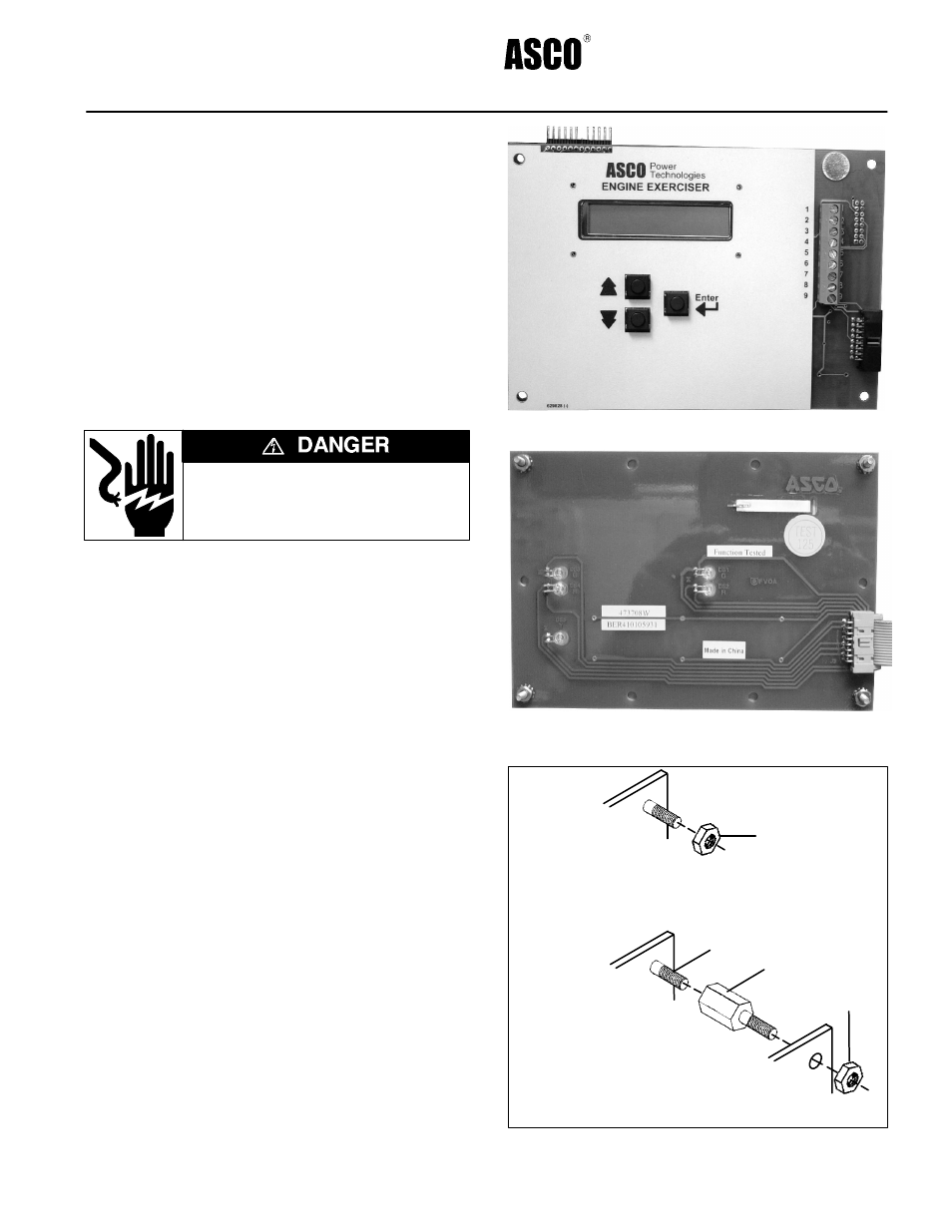
J1
Figure 1. Accessory 11BG Module in kits.
J3
Figure 2. Series 300 ATS operator Interface board
mounted on the enclosure door (back view).
original mounting of Series 300 ATS
operator interface on enclosure door
standoff added for Acc. 11BG Module
add 4 standoffs
install Acc. 11BG board
operator
interface
board
stud
reinstall
4 nuts
remove 4 nuts
(with captive
lockwashers)
Step 1
Step 2
Step 3
Figure 3. Module installation hardware.