Connecting the loads – Winco ULTB4000C User Manual
Page 6
12024-00
6
60706-225
tor. However, due to engine and generator effi cien-
cies of 80 to 90%, the loss of power due to engine
driving accessories such as cooling fans, battery
charging alternators, etc., friction losses and slippage
in the drive pullies and belts, the general conserva-
tive rule of thumb allowing approximately two (2)
horsepower for every 1,000 watts of generator output
is much more realistic. For example, this 2,000 watt
generator output will require a 4 or 5 H.P. engine
for full output, good speed/voltage regulation, and
satisfactory load performance. When determining the
prime mover/generator pulley ratio to drive the gen-
erator at the correct operating speed, bear in mind
that the power rating of most prime movers (usually
an engine) varies with the speed. It produces more
power at higher speeds, less when slowed. The
prime mover must be run fast enough to reach the
desired horsepower for good generator operation.
The drive belt system must be of adequate size and
must be tight enough to power the generator without
slippage. Be careful not to overtighten to the extent
that it puts excessive strain on the bearings. Doing
so can cause bearing failure and other possible dam-
age to the generator.
Alignment of the generator to the prime mover is
important. Misalignment of the pulleys will cause ex-
cessive belt and pulley wear and unnecessary stress
on the prime mover.
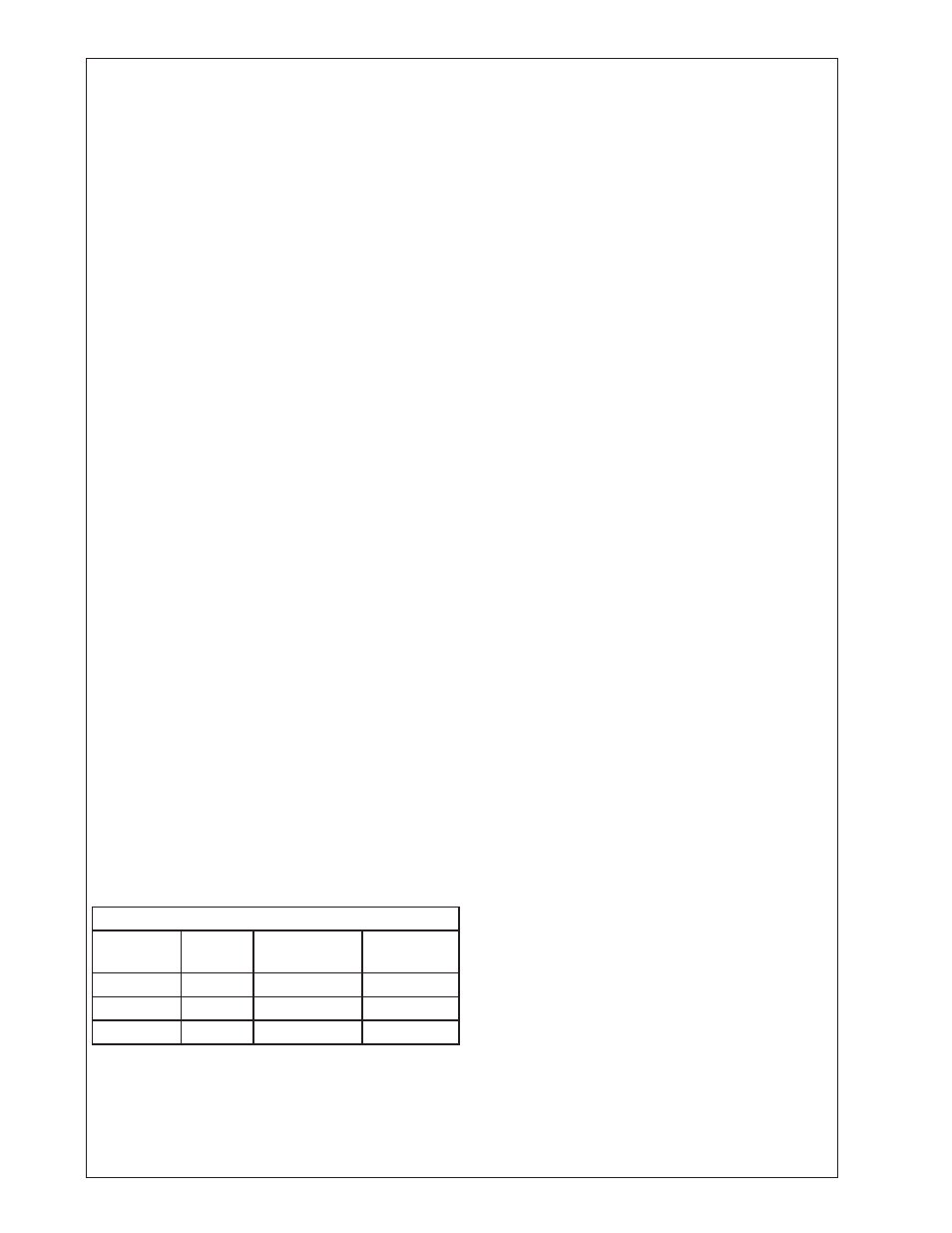
The following table shows the effect of various oper-
ating speeds and electrical loads on a typical gen-
erator when matched and mounted to an adequate
prime mover.
Although individual units and models may vary
slightly, the normal voltage and frequency of typical
60 cycle engine-driven generators described in this
manual are approximately as follows when powered
by a typical prime mover (engine) run fi rst with no
load applied, then at half the generator capacity and
fi nally when loaded to its full capacity as rated on the
nameplate.
LOAD VS. OUTPUT
Generator
Load*
Speed
(RPM)
Frequency
(Hz)
Voltage
None
3690
61.5
129V
Half
3600
60.0
120V
Full
3510
58.5
115V
* NOTE: Required generator speed must be main-
tained at 3600 +/- 90 RPM under all load conditions.
All engines have a tendency to slow down when
a load is applied. The governor on the engine is
designed to hold the engine speed nearly constant.
When the electrical load connected to the genera-
tor is increased, the engine is more heavily loaded
and as a result the speed drops slightly. This slight
decrease in speed together with the natural “voltage
drop” within the generator itself due to load current
and heating of the windings, results in a slightly
lower voltage than when the generator is running
idle.
The normal slight variations in speed also directly
affect the frequency of the output current. This
frequency variation has no appreciable effect in the
operation of most loads (such as motors, lights and
most small appliances). However, timing devices
and clocks will not keep perfect time unless the en-
gine can keep the generator running at exactly 3600
RPM at all times. Since this is not usually possible,
minor time errors in clocks occur.
The speed of the engine is usually adjusted so that
the generator produces proper voltage. If the adjust-
ment is made “cold,” set the voltage a little higher
than normal since it will drop a few volts as the
generator warms up.
NOTE: When operating continuously at full load the
generator shell becomes very warm. It will be un-
comfortable to the touch. This is normal for any high
performance inherently regulated generator. Output
voltage should be checked periodically to ensure
proper operation of the generator and appliances.
CAUTION: EQUIPMENT DAMAGE
Low voltage may damage any motors or appliances
connected to it. Running the generator at exces-
sively high speeds results in too high voltage which
will also damage electrical devices connected to it.
Excessively high speed may also cause damage to
the generator armature windings.
CONNECTING THE LOADS
Applying The Load - A short warm-up time will
permit the engine to work more effi ciently when the
load is applied and will reduce the wear and extend
its life. Receptacles have been provided on the end
cover to connect the loads on this generator.
CAUTION: EQUIPMENT OVERLOAD
Keep the generator load within the generator and re-
ceptacle nameplate rating. Overloading may cause
damage to the generator and/or the loads.
Most electric tools and appliances will have the volt-
age and amperage requirements on their individual
nameplates. When in doubt consult the manufactur-
er or a local electrician. The nameplate amperage