Testing policy, Description, Unit capabilities – Winco ULTB4000C User Manual
Page 4: Generator connections, Starting electric motors
12024-00
4
60706-225
TESTING POLICY
Before any generator is shipped from the factory, it
is fully checked for performance. The generator is
loaded to its full capacity, and the voltage, current
and frequency are carefully checked.
Rated output of generator is based on engineering
tests of typical units, and is subject to, and limited
by, the temperature, altitude, fuel, and other condi-
tions specifi ed by the manufacturer of the applicable
engines.
DESCRIPTION
The generator is a 3600 rpm two bearing, belt driv-
en, brushless, revolving fi eld design. The generator
is self excited and inherently regulated to +/- (plus or
minus) 7% - no load to full rated load. It can be op-
erated under any load within its rating without being
damaged. The frequency regulation is determined
by the sensitivity of the customer supplied prime
movers’ governor. It is desirable to maintain this
speed to within 3 cycles variation (61.5 Hz - 58.5 Hz)
no load to full rated load (3690 rpm - 3510 rpm).
UNIT CAPABILITIES
GENERATOR CONNECTIONS
This generator is designed for 120/240 volt alter-
nating current (AC). Two circuit breaker protected
duplex outlets and one 240 volt twist lock receptacle
are provided for connection to various loads. This
generator can be spun in either direction.
FULL POWER 120 VOLT ONLY
This generator can be converted to full power 120
volt only. Replacement of the circuit breaker and
receptacle is required. A 30 amp 1-pole circuit
breaker and a 3-wire 30 amp twist-lock receptacle is
recommended for full power applications. See wir-
ing schematic below.
Check the appliance or tool nameplate for the cur-
rent and voltage to insure compatibility. Although a
circuit breaker is provided, damage due to overload-
ing constitutes abuse and will not be warranted. Re-
fer to the generator nameplate for unit’s capabilities.
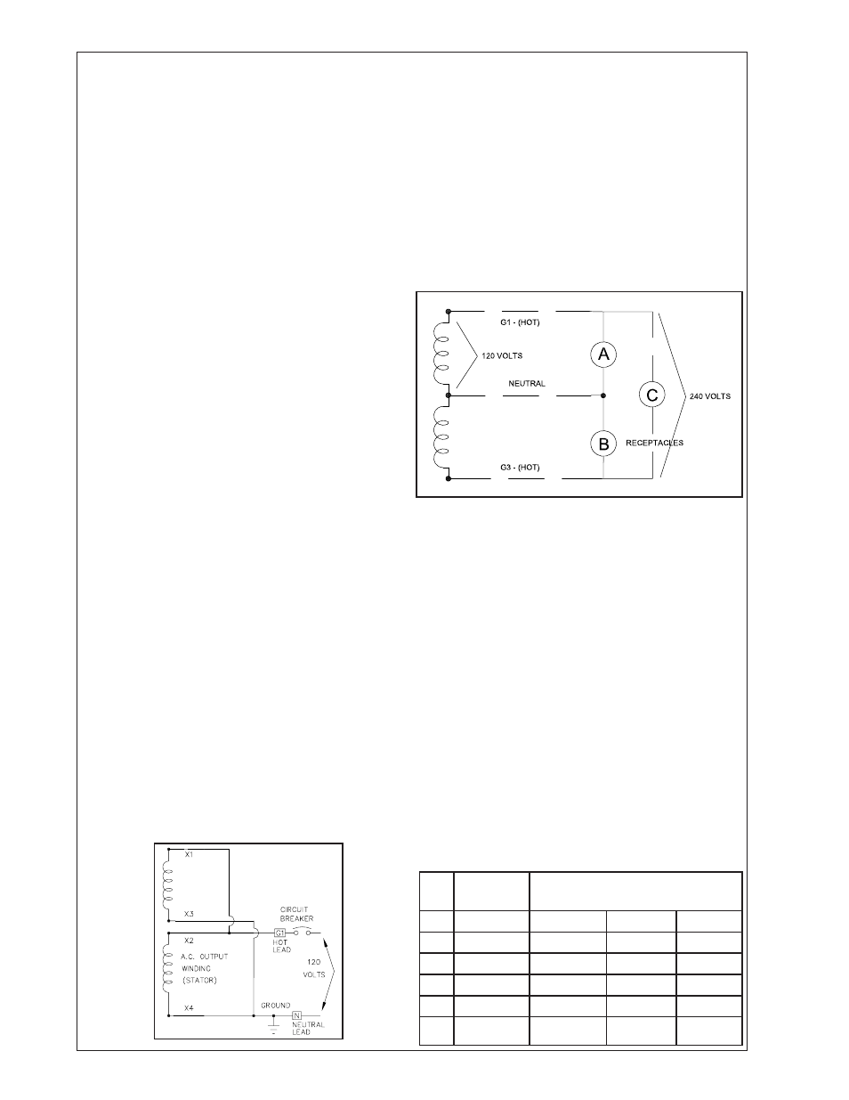
The diagram below represents a 4,000 watt genera-
tor. Only 2,000 watts at 120 volts (16.6 Amps) can
be taken from the generator at receptacle A and up
to 2,000 watts at 120 volts from receptacle C. On
an ordinary generator, CAUTION MUST BE EXER-
CISED TO PREVENT OVERLOADING EITHER OF
THE 120 VOLT CIRCUITS (A OR C).
STARTING ELECTRIC MOTORS
Electric motors require much more current (amps) to
start them than to run them. Some motors, par-
ticularly low cost split-phase motors, are very hard
to start and require 5 to 7 times as much current
to start them as to run them. Capacitor motors are
easier to start and usually require 2 to 4 times as
much current to start them as to run them. Repul-
sion Induction motors are the easiest to start and
require 1 1/2 to 2 1/2 times as much to start them as
to run them.
Most fractional horsepower motors take about the
same amount of current to run them whether they
are Repulsion Induction (RI), Capacitor (Cap), or
Split-Phase (SP) type. The chart below shows the
approximate current required to start and run various
types and sizes of 120 volt 60 cycle electric motors
under average load conditions.
HP
AMPS
RUNNING
STARTING AMPS
SP
CAP
RI
1/6
3.2
16 to 22
6 to 13
5 to 8
1/4
4.5
22 to 32
9 to 18
7 to 12
1/3
5.2
26 to 35
10 to 21
8 to 17
1/2
7.2
not made
14 to 29
11 to 18
1
13.0
not made
26 to 52
20 to 33